Subaru Legacy IV (2008 year). Service manual — part 912
ABS(diag)-47
Diagnostic Procedure with Diagnostic Trouble Code (DTC)
ABS (DIAGNOSTICS)
S: DTC C0109 POWER VOLTAGE MALFUNCTION
DTC DETECTING CONDITION:
Power supply voltage of the ABSCM&H/U is too low or too high.
TROUBLE SYMPTOM:
• ABS does not operate.
• EBD may not operate.
NOTE:
If EBD does not operate, the brake warning light illuminates in addition to ABS warning light. Both warning
lights go off if voltage returns.
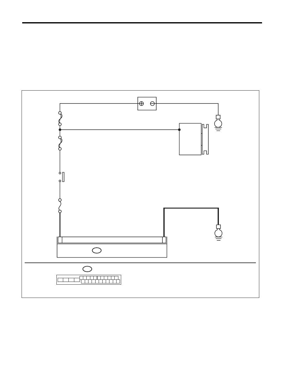
WIRING DIAGRAM:
ABS00805
MAIN SBF
SBF-6
No.33
B301
E
E
15
18
ABSCM & H/U
BATTERY
GENERATOR
IGNITION
SWITCH
B301
1 2 3 4 5 6 7 8 9 10 11
16 17 18 19 20 21 22 23 24 25 26
13
12
15
14

ABS(diag)-48
Diagnostic Procedure with Diagnostic Trouble Code (DTC)
ABS (DIAGNOSTICS)
Step
Check
Yes
No
1
CHECK GENERATOR.
1) Start the engine.
2) Run the engine at idle after warming up.
3) Measure the voltage between generator ter-
minal B and chassis ground.
Terminals
Generator B terminal (+) — Chassis
ground (–):
Is the voltage 10 — 15 V?
Go to step 2.
Repair the genera-
tor.
2
CHECK BATTERY TERMINAL.
Turn the ignition switch to OFF.
Are the positive and negative
battery terminals tightened
securely?
Go to step 3.
Tighten the termi-
nal.
3
CHECK INPUT VOLTAGE OF ABSCM&H/U.
1) Disconnect the ABSCM&H/U connectors.
2) Run the engine at idle.
3) Operate devices such as headlights, air
conditioner, defogger, etc. which produce an
electrical load.
4) Measure the voltage between ABSCM&H/U
connector and chassis ground.
Connector & terminal
(B301) No. 18 (+) — Chassis ground (–):
Is the voltage 10 — 15 V?
Go to step 4.
Repair the
ABSCM&H/U
power circuit.
4
CHECK THE ABSCM&H/U GROUND CIR-
CUIT.
1) Turn the ignition switch to OFF.
2) Measure the resistance between the
ABSCM&H/U connector and chassis ground.
Connector & terminal
(B301) No. 15 — Chassis ground:
Is the resistance less than 0.5
:? Go to step 5.
Repair the
ABSCM&H/U
ground harness.
5
CHECK POOR CONTACT IN CONNECTOR.
Is there poor contact in connec-
tor between generator, battery
and ABSCM&H/U?
Repair the connec-
tor.
Go to step 6.
6
CHECK ABSCM&H/U.
1) Connect all connectors.
2) Clear the memory. <Ref. to ABS(diag)-20,
Clear Memory Mode.>
3) Perform the Inspection Mode. <Ref. to
ABS(diag)-19, Inspection Mode.>
4) Read the DTC.
Is the same DTC displayed?
Replace the
ABSCM only. <Ref.
to ABS-8,
REPLACEMENT,
ABS Control Mod-
ule and Hydraulic
Control Unit
(ABSCM&H/U).>
Go to step 7.
7
CHECK FOR ANY OTHER DTC ON DISPLAY. Is any other DTC displayed?
Check DTC using
“List of Diagnostic
Trouble Code
(DTC)”. <Ref. to
ABS(diag)-29, List
of Diagnostic Trou-
ble Code (DTC).>
Temporary poor
contact occurs.
ABS(diag)-49
Diagnostic Procedure with Diagnostic Trouble Code (DTC)
ABS (DIAGNOSTICS)
T: DTC C0140 CAN COMMUNICATION MALFUNCTION
DTC DETECTING CONDITION:
Defective CAN communication
TROUBLE SYMPTOM:
Possibly the vehicle speed cannot output on CAN.
Step
Check
Yes
No
1
CHECK LAN SYSTEM.
Perform the diagnosis for LAN system. <Ref. to
LAN(diag)-27, OPERATION, Read Diagnostic
Trouble Code (DTC).>
Is there any fault in LAN sys-
tem?
Repair it according
to DTC of LAN sys-
tem.
Replace the
ABSCM only. <Ref.
to ABS-8,
REPLACEMENT,
ABS Control Mod-
ule and Hydraulic
Control Unit
(ABSCM&H/U).>
ABS(diag)-50
Diagnostic Procedure with Diagnostic Trouble Code (DTC)
ABS (DIAGNOSTICS)
U: DTC C0114 VALVE RELAY MALFUNCTION
DTC DETECTING CONDITION:
Defective valve relay
TROUBLE SYMPTOM:
• ABS does not operate.
• EBD does not operate depending on the trouble contents.
NOTE:
Brake warning light illuminates as well as ABS warning light when EBD does not operate.
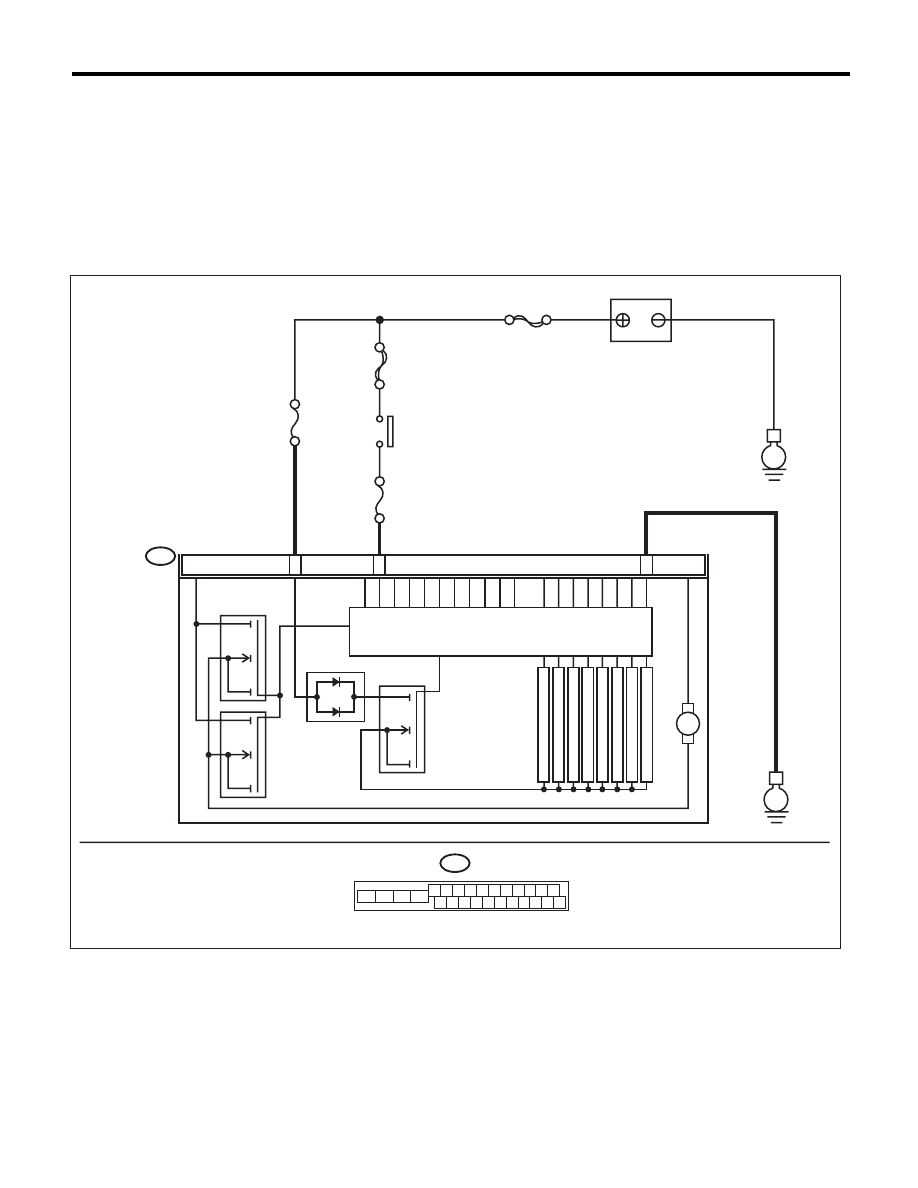
WIRING DIAGRAM:
B301
B301
E
14
15
ABSCM & H/U
18
M
F
L
INLET
MAIN SBF
SBF-6
No.1
No.33
E
F
R
INLET
R
L
INLET
R
R
INLET
FL OUTLET
FR OUTLET
RL OUTLET
RR OUTLET
4 5 6 7 8 9
16 17 18 19 20
2 3
1
21 22 23 24 25 26
10 11
13
14
12
15
ABS00996
BATTERY
IGNITION
SWITCH
MO
T
OR RELA
Y
VALVE RELAY
SOLENOID V
A
L
V
E
PUMP MOTOR
Нет комментариевНе стесняйтесь поделиться с нами вашим ценным мнением.
Текст