Subaru Legacy IV (2008 year). Service manual — part 913

ABS(diag)-51
Diagnostic Procedure with Diagnostic Trouble Code (DTC)
ABS (DIAGNOSTICS)
Step
Check
Yes
No
1
CHECK INPUT VOLTAGE OF ABSCM&H/U.
1) Turn the ignition switch to OFF.
2) Disconnect the ABSCM&H/U connectors.
3) Run the engine at idle.
4) Measure the voltage between ABSCM&H/U
connector and chassis ground.
Connector & terminal
(B301) No. 18 (+) — Chassis ground (–):
(B301) No. 14 (+) — Chassis ground (–):
Is the voltage 10 — 15 V?
Go to step 2.
Repair the harness
connector between
battery and
ABSCM&H/U.
2
CHECK THE ABSCM&H/U GROUND CIR-
CUIT.
1) Turn the ignition switch to OFF.
2) Measure the resistance between the
ABSCM&H/U connector and chassis ground.
Connector & terminal
(B301) No. 15 — Chassis ground:
Is the resistance less than 0.5
:? Go to step 3.
Repair the
ABSCM&H/U
ground harness.
3
CHECK VALVE RELAY IN ABSCM&H/U.
Measure the resistance between the
ABSCM&H/U terminals.
Terminals
No. 14 — No. 15:
Is the resistance 1 M
: or
more?
Go to step 4.
Replace the
ABSCM only. <Ref.
to ABS-8,
REPLACEMENT,
ABS Control Mod-
ule and Hydraulic
Control Unit
(ABSCM&H/U).>
4
CHECK POOR CONTACT IN CONNECTOR.
Is there poor contact in connec-
tor between generator, battery
and ABSCM&H/U?
Repair the connec-
tor.
Go to step 5.
5
CHECK ABSCM&H/U.
1) Connect all connectors.
2) Clear the memory. <Ref. to ABS(diag)-20,
Clear Memory Mode.>
3) Perform the Inspection Mode. <Ref. to
ABS(diag)-19, Inspection Mode.>
4) Read the DTC.
Is the same DTC displayed?
Replace the
ABSCM only. <Ref.
to ABS-8,
REPLACEMENT,
ABS Control Mod-
ule and Hydraulic
Control Unit
(ABSCM&H/U).>
Go to step 6.
6
CHECK FOR ANY OTHER DTC ON DISPLAY. Is any other DTC displayed?
Check DTC using
“List of Diagnostic
Trouble Code
(DTC)”. <Ref. to
ABS(diag)-29, List
of Diagnostic Trou-
ble Code (DTC).>
Temporary poor
contact occurs.
ABS(diag)-52
Diagnostic Procedure with Diagnostic Trouble Code (DTC)
ABS (DIAGNOSTICS)
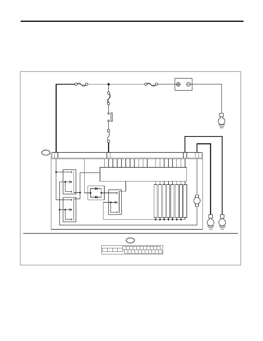
V: DTC C0111 MOTOR/MOTOR RELAY MALFUNCTION
DTC DETECTING CONDITION:
• Defective motor
• Defective motor relay
• Defective harness connector
TROUBLE SYMPTOM:
ABS does not operate.
WIRING DIAGRAM:
B301
E
E
13
15
12
ABSCM & H/U
18
M
MAIN SBF
SBF-6
No.33
E
SBF-1
FL INLET
FR INLET
RL INLET
RR INLET
FL OUTLET
FR OUTLET
RL OUTLET
RR OUTLET
B301
4 5 6 7 8 9
16 17 18 19 20
2 3
1
21 22 23 24 25 26
10 11
13
14
12
15
ABS00997
PUMP MOTOR
BATTERY
IGNITION
SWITCH
MOTOR RELAY
VALVE RELAY
SOLENOID VALVE

ABS(diag)-53
Diagnostic Procedure with Diagnostic Trouble Code (DTC)
ABS (DIAGNOSTICS)
Step
Check
Yes
No
1
CHECK INPUT VOLTAGE OF ABSCM&H/U.
1) Turn the ignition switch to OFF.
2) Disconnect the ABSCM&H/U connectors.
3) Turn the ignition switch to ON.
4) Measure the voltage between ABSCM&H/U
connector and chassis ground.
Connector & terminal
(B301) No. 13 (+) — Chassis ground (–):
Is the voltage 10 — 15 V?
Go to step 2.
Repair the harness
connector between
battery and
ABSCM&H/U.
2
CHECK INSTALLATION OF MOTOR
GROUND.
Is the motor ground terminal
installation bolt tightened to
33 N·m (3.3 kgf-m, 24.3 ft-lb)?
Go to step 3.
Tighten the motor
ground terminal
installation bolt.
3
CHECK GROUND CIRCUIT OF MOTOR.
1) Turn the ignition switch to OFF.
2) Measure the resistance between the
ABSCM&H/U connector and chassis ground.
Connector & terminal
(B301) No. 12 — Chassis ground:
Is the resistance less than 0.5
:? Go to step 4.
Repair the
ABSCM&H/U
ground harness.
4
CHECK INPUT VOLTAGE OF ABSCM&H/U.
1) Run the engine at idle.
2) Measure the voltage between ABSCM&H/U
connector and chassis ground.
Connector & terminal
(B301) No. 18 (+) — Chassis ground (–):
Is the voltage 10 — 15 V?
Go to step 5.
Repair the harness
connector between
battery, ignition
switch and
ABSCM&H/U.
5
CHECK THE ABSCM&H/U GROUND CIR-
CUIT.
1) Turn the ignition switch to OFF.
2) Measure the resistance between the
ABSCM&H/U connector and chassis ground.
Connector & terminal
(B301) No. 15 — Chassis ground:
Is the resistance less than 0.5
:? Go to step 6.
Repair the
ABSCM&H/U
ground harness.
6
CHECK POOR CONTACT IN CONNECTOR.
Turn the ignition switch to OFF.
Is there poor contact in connec-
tor between generator, battery
and ABSCM&H/U?
Repair the connec-
tor.
Go to step 7.
7
CHECK ABSCM&H/U.
1) Connect all connectors.
2) Clear the memory. <Ref. to ABS(diag)-20,
Clear Memory Mode.>
3) Perform the Inspection Mode. <Ref. to
ABS(diag)-19, Inspection Mode.>
4) Read the DTC.
Is the same DTC displayed?
Replace the
ABSCM&H/U.
<Ref. to ABS-6,
ABS Control Mod-
ule and Hydraulic
Control Unit
(ABSCM&H/U).>
Go to step 8.
8
CHECK FOR ANY OTHER DTC ON DISPLAY. Is any other DTC displayed?
Check DTC using
“List of Diagnostic
Trouble Code
(DTC)”. <Ref. to
ABS(diag)-29, List
of Diagnostic Trou-
ble Code (DTC).>
Temporary poor
contact occurs.
NOTE:
Though the ABS
warning light re-
mains on at this
time, this is normal.
Drive the vehicle at
12 km/h (7 MPH)
or more in order to
turn ABS warning
light off. Be sure to
drive the vehicle
and check that the
warning light goes
off.
ABS(diag)-54
Diagnostic Procedure with Diagnostic Trouble Code (DTC)
ABS (DIAGNOSTICS)
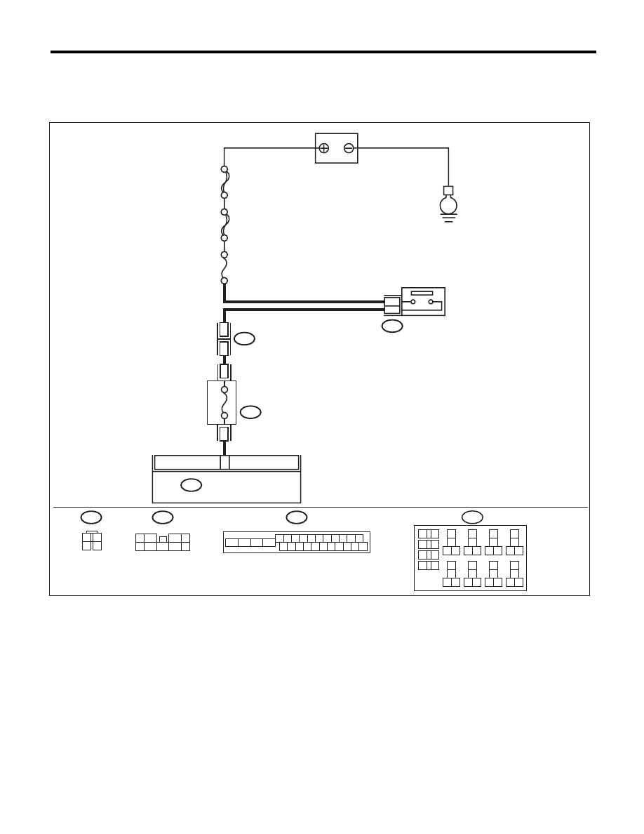
W: DTC C0116 FAULTY STOP LIGHT SWITCH
DTC DETECTING CONDITION:
Defective stop light switch
WIRING DIAGRAM:
MAIN SBF
SBF-2
No.8
7.5A
B301
2
3
E
20
ABSCM & H/U
B65
9
5
B159
3
4
B225
1 2 3 4 5 6 7 8 9 10 11
16 17 18 19 20 21 22 23 24 25 26
13
12
15
14
9
4
7
6
2
1
5
3
8
B159
B301
B65
1
2
3
4
B225
13
14
15 16
17
27
24
25
26
20
21
22
23
29
30
31
28
32
35
33
34
37
38
39
36
40
8
9
10
11 12
1
2
5
3
4
7
6
19
18
ABS00998
BATTERY
STOP LIGHT
SWITCH
FUSE
(RELAY BLOCK)
Нет комментариевНе стесняйтесь поделиться с нами вашим ценным мнением.
Текст