Subaru Legacy IV (2008 year). Service manual — part 200
GD(H4SO)-102
Diagnostic Trouble Code (DTC) Detecting Criteria
GENERAL DESCRIPTION
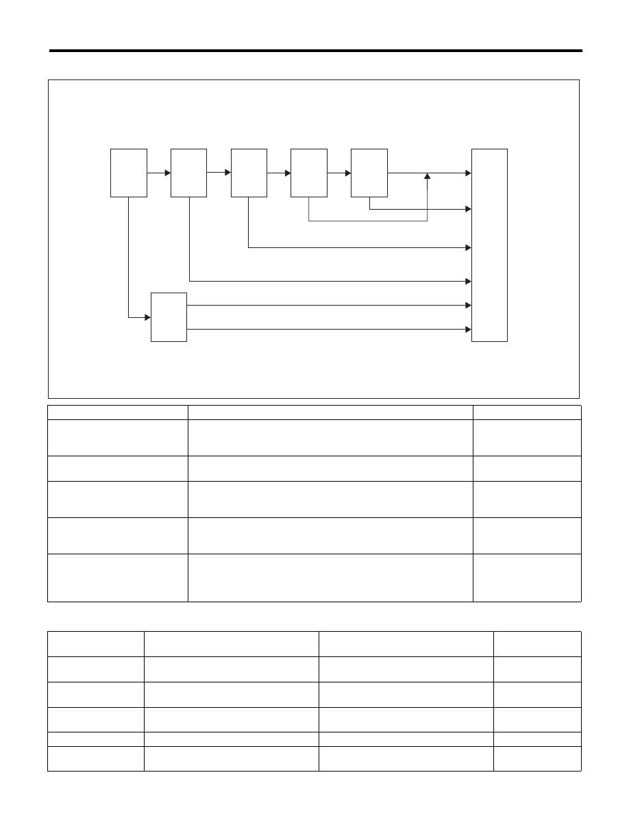
0.04-inch Diagnosis
Mode Table for Evaporative Emission Control System Diagnosis
Mode
Mode Description
Diagnosis Period
Mode Z
(Purge control solenoid valve
opening failure diagnosis)
Perform purge control solenoid valve opening failure diagnosis from
the size of tank pressure variation from diagnosis start.
0 ms + 3000 ms — 0 ms
+ 3000 ms + 13000 ms
Mode A
(Estimated evaporation amount)
Calculate the tank pressure change amount (P1).
10000 ms
Mode B
(Sealed negative pressure,
large leakage judgment)
Decrease the pressure in the tank to the target value by introducing
the intake manifold pressure to the fuel tank.
If the tank pressure cannot be reduced, it is diagnosed as large leak.
0 — 10000 ms
+ 25000 ms
Mode C
(Pressure increase check,
advanced OK judgment)
Wait until the tank pressure returns to the target (start level of P2
calculation). If the tank pressure does not become the value, make
advanced OK judgment.
0 — 18500 ms
Mode D
(Negative pressure variation
measurement, evaporation
leakage diagnosis)
Calculate the tank pressure variation (P2), and obtain the diagnostic
value using P1 found in Mode A.
Perform the evaporation diagnosis using the diagnostic value.
0 ms + 10000 ms
Mode
Behavior of tank internal pressure under
normal conditions
Diagnostic item
DTC
Mode Z
Roughly the same as barometric pres-
sure (Same as 0 kPa (0 mmHg, 0 inHg))
Purge control solenoid valve is judged to
be open.
P0457
Mode A
Pressure is in proportion to amount of
evaporative emission.
—
None
Mode B
Negative pressure is formed due to
intake manifold negative pressure
Large leak
P0457
Mode C
Reaches target pressure
—
None
Mode D
Pressure change is small.
EVAP system large leak determination.
[1.0 mm (0.04 in)]
P0442
Mode
Z
Mode
A
Mode
B
Mode
C
Mode
D
OK
OK
OK
OK
OK
NG
Early OK
Large leakage judgement
Cancel
Mode
Z
Extend
NG
NG
OK
END
EN-02872
GD(H4SO)-103
Diagnostic Trouble Code (DTC) Detecting Criteria
GENERAL DESCRIPTION
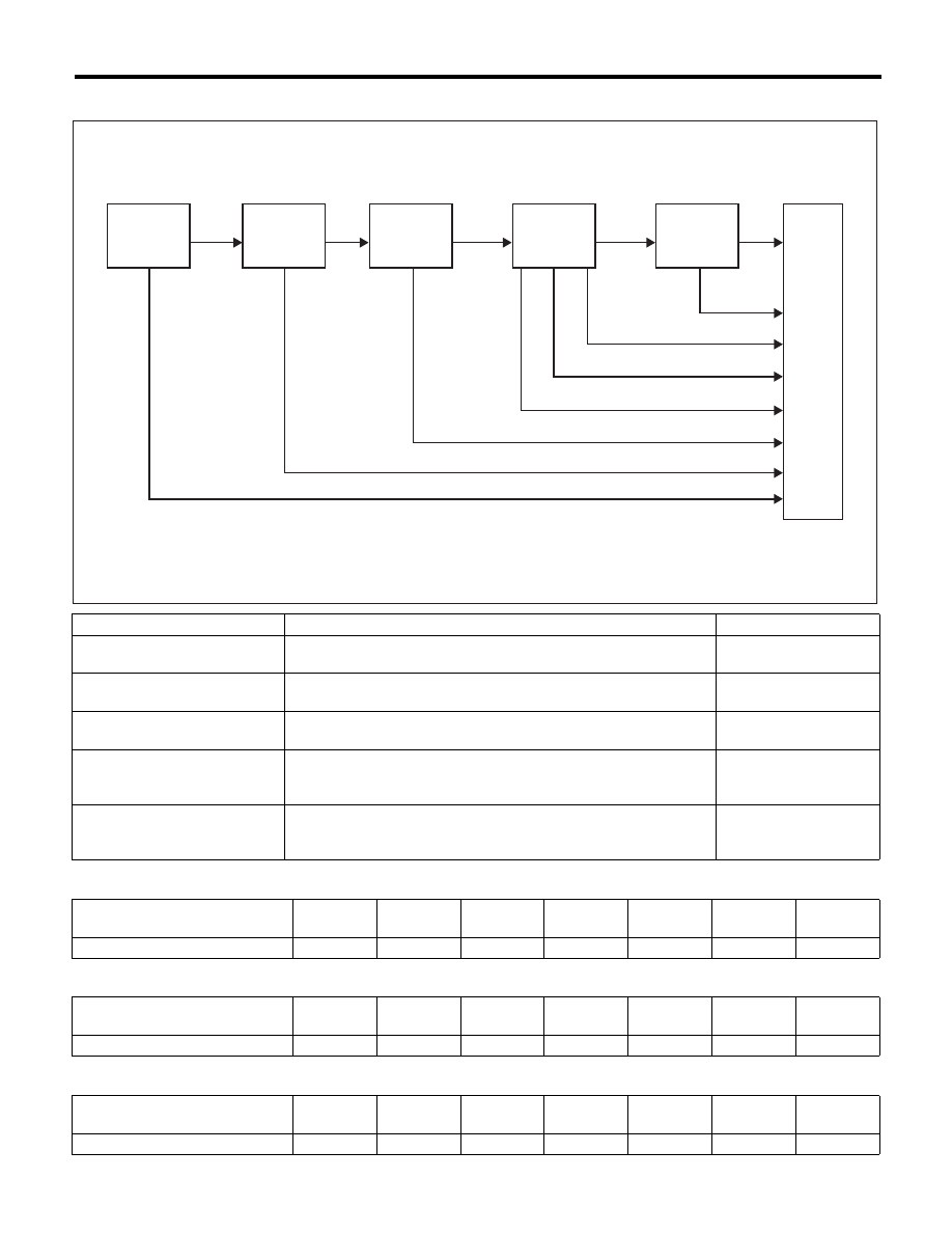
0.02-inch Diagnosis
Mode
Mode Description
Diagnosis Period
Mode A
(0 point compensation)
When the pressure in the tank is not near 0 mmHg, wait until it
returns to 0 point (near 0 mmHg).
0 — Value of Map 1
Mode B
(Negative pressure introduced)
Decrease the pressure in the tank to the target value by introducing
the intake manifold pressure to the fuel tank.
0 — Value of Map 2
Mode C
(Negative pressure maintained)
Wait until the tank pressure returns to the target (start level of P2
calculation).
0 — 20000 ms + 0
+ Value of Map 2
Mode D
(Negative pressure change
calculated)
Calculate the time it takes for the tank pressure to change to the
Mode E shifting pressure. If the tank pressure does not change to
the Mode E shifting pressure, make advanced OK judgment.
0 — 0 ms + 200000 ms
Mode E
(Evaporation generated amount
calculation)
Calculate the amount of evaporation (P1).
0 — 0 ms + 200000 ms
+ Value of Map 3
Map1
Fuel level (
2, US gal, Imp gal)
0
10, 2.64,
2.2
20, 5.28,
4.4
30, 7.93,
6.6
40, 10.57,
8.8
50, 13.21,
11
60, 15.85,
13.2
Time Needed for Diagnosis (ms)
12000
12000
11000
10000
7500
5000
5000
Map2
Fuel level (
2, US gal, Imp gal)
0
10, 2.64,
2.2
20, 5.28,
4.4
30, 7.93,
6.6
40, 10.57,
8.8
50, 13.21,
11
60, 15.85,
13.2
Time Needed for Diagnosis (ms)
21000
21000
21500
22000
22000
22000
22000
Map 3
Fuel level (
2, US gal, Imp gal)
0
10, 2.64,
2.2
20, 5.28,
4.4
30, 7.93,
6.6
40, 10.57,
8.8
50, 13.21,
11
60, 15.85,
13.2
Time Needed for Diagnosis (ms)
60000
60000
60000
60000
60000
60000
60000
EN-02871
Mode A
Mode B
Mode C
Mode D
Mode E
Cancel
Early OK 2
Early OK 1
OK
OK
OK
OK
Cancel
Cancel
Cancel
Cancel
END
GD(H4SO)-104
Diagnostic Trouble Code (DTC) Detecting Criteria
GENERAL DESCRIPTION
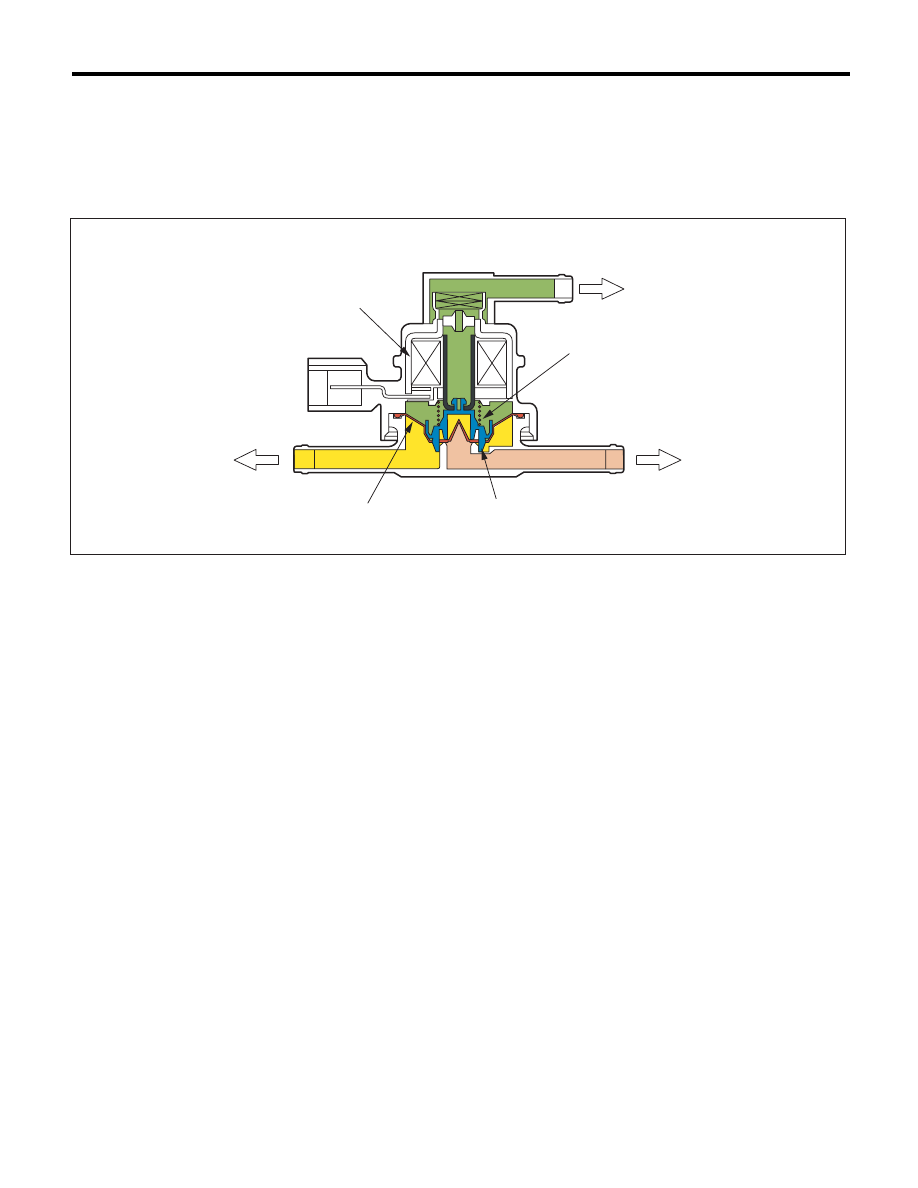
2. COMPONENT DESCRIPTION
Pressure control solenoid valve
PCV controls the fuel tank pressure to be equal to the atmospheric air pressure. Normally, the solenoid is set
to OFF. The valve opens and closes mechanically in accordance with the pressure difference between tank
and atmospheric air, or tank and canister.
The valve is forcibly opened by setting the solenoid to ON at the time of diagnosis.
(a)
Barometric pressure
(b)
Fuel tank
(c)
Canister
(1)
Solenoid
(3)
Valve
(4)
Spring
(2)
Diaphragm
EN-01715
(a)
(b)
(c)
(4)
(1)
(2)
(3)
GD(H4SO)-105
Diagnostic Trouble Code (DTC) Detecting Criteria
GENERAL DESCRIPTION
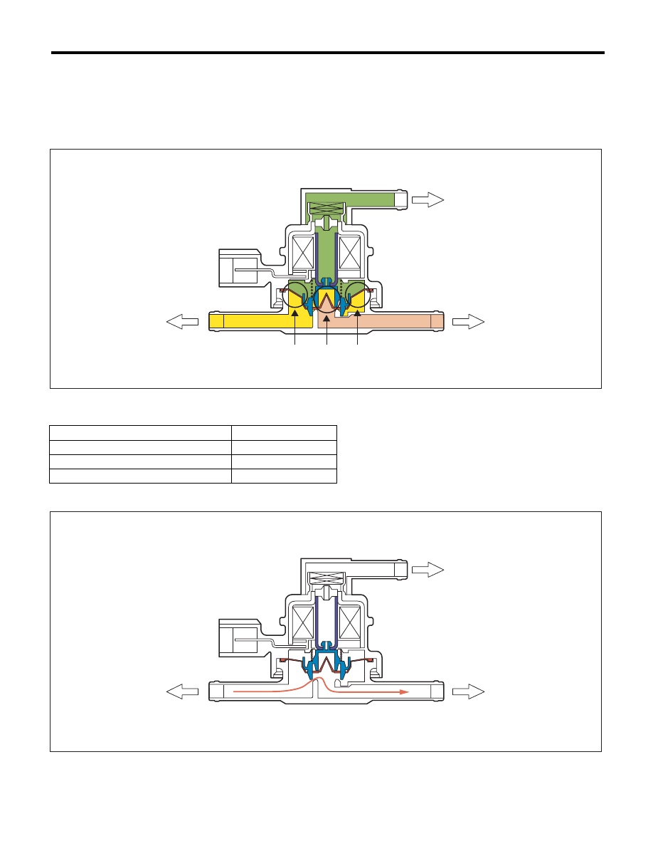
Valve Operation and Air Flow
In the figure below, divided by the diaphragm, the part above X is charged with atmospheric air pressure, and
the part below X is charged with tank pressure. Also, the part above Y is charged with tank pressure, and the
part below Y is charged with canister pressure.
If the atmospheric air pressure port is A, tank pressure port is B, and canister pressure port is C, the air flows
according to pressure difference from each port as shown in the table below.
When A < B (solenoid OFF)
(a)
Barometric pressure
(b)
Fuel tank
(c)
Canister
Condition of pressure
Flow
A < B (solenoid OFF)
B
o C
B < C (solenoid OFF)
C
o B
Solenoid ON
B
m o C
(a)
Barometric pressure
(b)
Fuel tank
(c)
Canister
EN-01716
A
B
C
X
X
Y
(a)
(b)
(c)
EN-01717
A
B
C
(a)
(b)
(c)
Нет комментариевНе стесняйтесь поделиться с нами вашим ценным мнением.
Текст