Subaru Legacy IV (2008 year). Service manual — part 199
GD(H4SO)-98
Diagnostic Trouble Code (DTC) Detecting Criteria
GENERAL DESCRIPTION
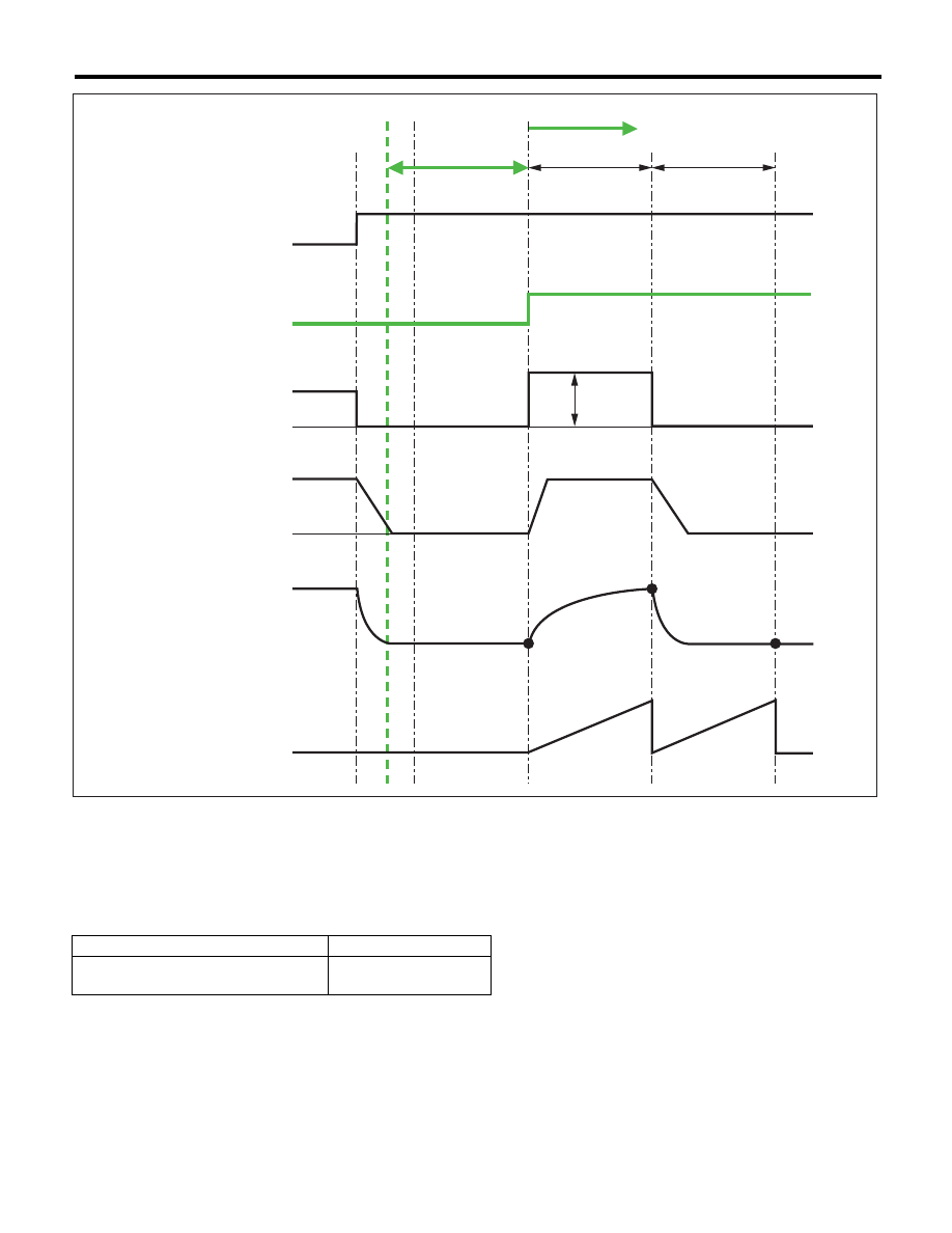
• Normality Judgement
Judge as OK and clear the NG if the following conditions are established.
Time Needed for Diagnosis: 1 time
(A)
3000 ms
(C)
1000 ms
(D)
45 step(s)
(B)
1000
ms
Judgement Value
Malfunction Criteria
Threshold Value
PMON – (PMOF1 + PMOF2)/2
t 2.5 kPa (18.63 mmHg,
0.7 inHg)
EN-05568
ON
OFF
(Open)
(Close)
(Open)
(Close)
PMOF1
PMON
PMOF2
Deceleration fuel cut
Diagnosis enable condition
EGR target step
EGR actual step
DIagnostic mode timer
Start dignosis
(D)
(A)
(B)
(C)
Intake manifold pressure
(During normal condition)
GD(H4SO)-99
Diagnostic Trouble Code (DTC) Detecting Criteria
GENERAL DESCRIPTION
BE:DTC P0420 CATALYST SYSTEM EFFICIENCY BELOW THRESHOLD (BANK 1)
1. OUTLINE OF DIAGNOSIS
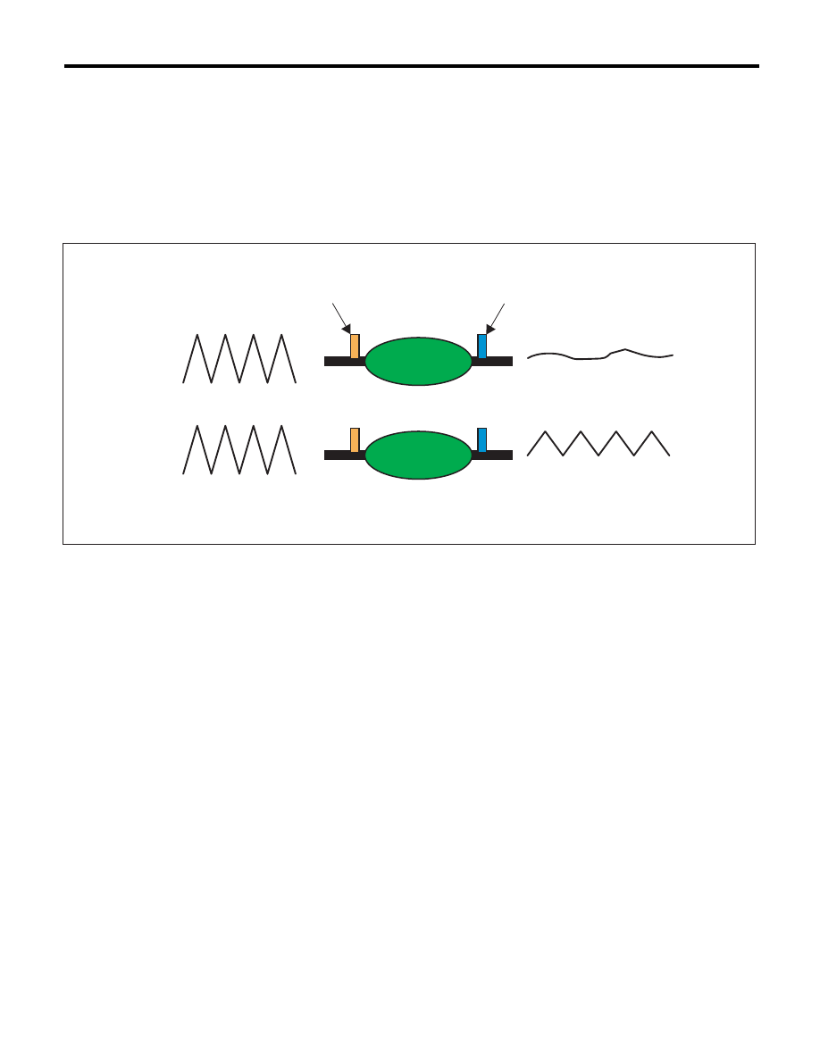
Detect the deterioration of the catalyst function.
Though the front oxygen sensor output would change slowly with a new catalyst, the sensor output with a de-
teriorated catalyst becomes high and the inversion time is shortened.
For this reason, the catalyst diagnosis is carried out by monitoring the front oxygen sensor output and com-
paring it with the front oxygen (A/F) sensor output.
2. COMPONENT DESCRIPTION
(A)
Normal
(C)
Output waveform from the front
oxygen (A/F) sensor
(D)
Output waveform from the rear
oxygen Sensor
(B)
Deterioration
(1)
Front oxygen (A/F) sensor
(2)
Front oxygen sensor
(3)
Catalytic converter
EN-01713
(A)
(B)
(C)
(D)
(1)
(2)
(3)
(3)

GD(H4SO)-100
Diagnostic Trouble Code (DTC) Detecting Criteria
GENERAL DESCRIPTION
3. ENABLE CONDITION
4. GENERAL DRIVING CYCLE
Perform the diagnosis only once at a constant 70 km/h (43.5 MPH) or higher.
5. DIAGNOSTIC METHOD
After establishing the execution conditions, calculate the front oxygen (A/F) sensor lambda deviation cumu-
lative value (
6 |(sglmd
n
– sglmd
n–1
)|) and rear oxygen sensor output voltage deviation cumulative value (
6
|(ro2sad
n
– ro2sad
n–1
)|) per 32 milliseconds × 4 , and when the front oxygen (A/F) sensor lambda deviation
cumulative value (
6 |(sglmd
n
– sglmd
n–1
)|) becomes the predetermined value or more, calculate the diag-
nostic value.
• Abnormality Judgement
If the duration of time while the following conditions are met is within the time indicated, judge as NG.
Time Needed for Diagnosis: 30 — 55 seconds
Malfunction Indicator Light Illumination: Illuminates when malfunction occurs in 2 continuous driving cy-
cles.
• Normality Judgement
Judge as OK and clear the NG if the continuous time while the following conditions are established is within
the predetermined time.
Time Needed for Diagnosis: 30 — 55 seconds
Secondary Parameters
Enable Conditions
Battery voltage
t 10.9 V
Atmospheric pressure
t 75 kPa (563 mmHg, 22.2 inHg)
Engine coolant temperature
t 70 °C (158 °F)
Estimated catalyst temperature
t 600 °C (1112 °F) (AT model)
t 585 °C (1085 °F) (MT model)
Misfire detection every 200 rotations
< 5 time(s)
Learning value of evaporation gas density
< 0.2
Sub feedback
In operation
Evaporative system diagnosis
Not in operation
Time of difference (< 0.10) between actual
lambda and target lambda
t 1000 ms
Vehicle speed
> 70 km/h (43.5 MPH)
Amount of intake air
t 10 g/s (0.35 oz/s)
and
< 40 g/s (1.41 oz/s)
Engine load change every 0.5 engine speed. < 0.02 g/rev (0 oz/rev)
Rear oxygen output change from 660 mV or
less to 660 mV or more
Experienced after fuel cut
Elapsed time after starting the engine
t 205 s
Purge execution calculated time
t 0 s
Judgement Value
Malfunction Criteria
Threshold Value
6 |(ro2sad
n
– ro2sad
n–1
)| /
6 |(sglmd
n
–
sglmd
n–1
)|
> 10 (U5 model)
> 15.5
(Except for U5 model)
Judgement Value
Malfunction Criteria
Threshold Value
6 |(ro2sad
n
– ro2sad
n–1
)| /
6 |(sglmd
n
–
sglmd
n–1
)|
d 10 (U5 model)
d 15.5
(Except for U5 model)
GD(H4SO)-101
Diagnostic Trouble Code (DTC) Detecting Criteria
GENERAL DESCRIPTION
BF:DTC P0442 EVAPORATIVE EMISSION CONTROL SYSTEM LEAK DETECTED
(SMALL LEAK)
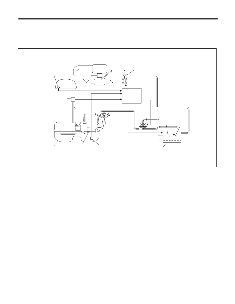
1. OUTLINE OF DIAGNOSIS
Check if there is a leakage in fuel system or not, and perform the function diagnosis of valve.
In this system diagnosis, check for leakage and valve function is conducted by changing the fuel tank pres-
sure and monitoring the pressure change using the fuel tank pressure sensor. When in 0.04 inch diagnosis,
perform in the order of mode Z
o mode A o mode B o mode C and mode D; When in 0.02 inch diagnosis,
perform in the order of mode A
o mode B o mode C o mode D and mode E.
(1)
Fuel gauge
(7)
Pressure control valve
(12)
Fuel level sensor
(2)
Intake manifold
(8)
Drain valve
(13)
Fuel tank
(3)
Throttle body
(9)
Drain filter
(14)
Fuel cut valve
(4)
Purge control solenoid valve
(10)
Shut-off valve
(15)
Fuel tank pressure sensor
(5)
Engine control module (ECM)
(11)
Fuel temperature sensor
(16)
Vent valve
(6)
Canister
(1)
(2)
(3)
(4)
(5)
(7)
(8)
(9)
(6)
(11)
(10)
(12)
(13)
(16)
(14)
(15)
EN-04151
Нет комментариевНе стесняйтесь поделиться с нами вашим ценным мнением.
Текст