Subaru Legacy IV (2008 year). Service manual — part 1094
IDI-17
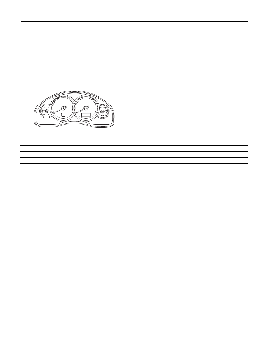
Combination Meter System
INSTRUMENTATION/DRIVER INFO
12.COMMUNICATION ERROR DISPLAY
When the following error code is displayed in the
odo/trip meter, inspect the communication circuit
since the communication failure is generated be-
tween each control module. <Ref. to LAN(diag)-2,
Basic Diagnostic Procedure.>
Since the communication error is not displayed on
the multi-information display meter, perform the in-
spection by referring to the “Basic Diagnostic Pro-
cedure” on the LAN(diag) section.
IDI00223
Error code
Remarks
Er IU
Malfunction in integrated unit
Er ––
Simultaneous malfunction of high/low speed CAN communication
Er HC
High speed CAN communication failure
Er LC
Low-speed CAN communication failure
Er EG
EGI communication failure
Er TC
TCM communication failure
Er Ab
ABS/VDC communication failure
Er SP
ABS/VDC DTC information and vehicle speed pulse malfunction
Er SS
Wheel speed data malfunction
IDI-18
Combination Meter System
INSTRUMENTATION/DRIVER INFO
13.DTC DISPLAY MODE
It is possible to display the DTC of the combination meter through the following procedures.
1) Within 3 seconds after turning the ignition switch to ON, set the lighting switch to tail light or headlight po-
sition.
2) Press the odo/trip meter knob four times.
3) Turn the lighting switch to OFF, and press the odo/trip meter knob four times.
4) Set the lighting switch to tail light or headlight position again, and press the odo/tripmeter knob four times.
NOTE:
• Perform the steps described in 2) and 4) within 10 seconds.
• When the engine starts during diagnosis, the self-diagnosis function is not cancelled, however, once turn-
ing the ignition switch to OFF or the vehicle starts driving, DTC display mode is cancelled automatically for
safety.
• When the DTC display mode operates, {ECM}, {TCM}, {ABS/VDC} is displayed cyclically in this order for
every three seconds or every press of the trip knob. DTC is displayed in the following table according to type
of control module, receiving DTC, DTC detected, No DTC.
• Past problems are displayed on the DTC display. When the DTC of individual control modules changes in
status from current trouble to past trouble, and the trouble is fixed, the DTC will no longer appear in the com-
bination meter if the engine is started three times or more.
• Normal meter
• Meter with multi-information display
NOTE:
Because the MT model is not equipped with a TCM, only “Receiving DTC” is displayed.
Control module
Condition
Display
ECM
Receiving DTC
Trip “A” + “P (Blink)”
DTC detected
Trip “A” + “P xxxx”
No DTC
Trip “A” + “P ----”
TCM
Receiving DTC
Trip “B” + “P (Blink)”
DTC detected
Trip “B” + “P xxxx”
No DTC
Trip “B” + “P ----”
ABS/VDCCM
Receiving DTC
Trip “A” + “C (Blink)”
DTC detected
Trip “A” + “C xxxx”
No DTC
Trip “A” + “C ----”
When CAN communication error
is occurred
—
“----”
Control module
Multi screen
Condition
Multi display
ECM
EGI fail code
Receiving DTC
“P” blinking
P xxxx DTC detected
“P xxxx”
No DTC
“P ----”
TCM
TCM fail code
Receiving DTC
“P” blinking
P xxxx DTC detected
“P xxxx”
No DTC
“P ----”
ABS/VDCCM
ABS fail code
Receiving DTC
“C” blinking
P xxxx DTC detected
“C xxxx”
No DTC
“C ----”
When CAN communication error
is occurred
Body CAN fail
—
—
-----
IDI-19
Clock System
INSTRUMENTATION/DRIVER INFO
3. Clock System
A: WIRING DIAGRAM
1. CLOCK
<Ref. to WI-178, WIRING DIAGRAM, Clock System.>
B: INSPECTION
1. SYMPTOM CHART
2. CHECK POWER SUPPLY AND GROUND CIRCUIT
3. CHECK ILLUMINATION CIRCUIT
Symptoms
Repair order
Reference
No display is shown.
1. Power supply
2. Clock body
<Ref. to IDI-19, CHECK POWER SUPPLY AND
GROUND CIRCUIT, INSPECTION, Clock System.>
Illumination does not illuminate.
1. Illumination power supply
2. Clock body
<Ref. to IDI-19, CHECK ILLUMINATION CIRCUIT,
INSPECTION, Clock System.>
“Acc” or “ign” is displayed.
ACC or ignition power supply
<Ref. to IDI-20, CHECK ACC OR IGNITION POWER
SUPPLY, INSPECTION, Clock System.>
“Err” is displayed in all items.
1. Communication circuit between
combination meter and clock
2. Clock body
<Ref. to IDI-20, CHECK COMMUNICATION CIR-
CUIT, INSPECTION, Clock System.>
“Err” is displayed when a particu-
lar item is selected.
Communication circuit between com-
bination meter and individual control
modules
<Ref. to IDI-17, COMMUNICATION ERROR DIS-
PLAY, INSPECTION, Combination Meter System.>
“Err” is displayed on the display of
the ambient temperature.
1. Ambient sensor
2. Clock body
<Ref. to IDI-20, CHECK AMBIENT SENSOR,
INSPECTION, Clock System.>
“Err” is displayed on the Instanta-
neous fuel economy, Average fuel
economy, and the Remaining dis-
tance.
1. Communication circuit between
combination meter and individual
control modules
2. Clock body
<Ref. to IDI-17, COMMUNICATION ERROR DIS-
PLAY, INSPECTION, Combination Meter System.>
Step
Check
Yes
No
1
CHECK CLOCK POWER SUPPLY.
1) Disconnect the clock harness connector.
2) Measure the voltage between the clock har-
ness connector and chassis ground.
Connector & terminal
(i59) No. 10 (+) — Chassis ground (–):
Is the voltage 10 V or more?
Go to step 2.
Check the harness
for a open or short
between the fuse
and clock.
2
CHECK CLOCK GROUND CIRCUIT.
1) Turn the ignition switch to OFF.
2) Measure the resistance between the clock
harness connector and chassis ground.
Connector & terminal
(i59) No. 6 — Chassis ground:
Is the resistance less than 10
:? Replace the clock
body.
Repair the wiring
harness.
Step
Check
Yes
No
1
CHECK ILLUMINATION CIRCUIT POWER
SUPPLY.
1) Turn the ignition switch to OFF.
2) Disconnect the clock harness connector.
3) Turn the ignition switch and lighting switch to
ON.
4) Measure the voltage between the clock har-
ness connector and chassis ground.
Connector & terminal
(i59) No. 1 (+) — Chassis ground (–):
Is the voltage 10 V or more?
Replace the clock
body.
Check the harness
for a open or short
between the fuse
and clock.
IDI-20
Clock System
INSTRUMENTATION/DRIVER INFO
4. CHECK ACC OR IGNITION POWER SUPPLY
5. CHECK COMMUNICATION CIRCUIT
6. CHECK AMBIENT SENSOR
Step
Check
Yes
No
1
CHECK ACC POWER SUPPLY.
1) Turn the ignition switch to OFF.
2) Disconnect the clock harness connector.
3) Turn the ignition switch to ACC.
4) Measure the voltage between the clock har-
ness connector and chassis ground.
Connector & terminal
(i59) No. 9 (+) — Chassis ground (–):
Is the voltage 10 V or more?
Go to step 2.
Check for open cir-
cuits in the har-
ness between the
fuse and the clock.
2
CHECK THE IGNITION POWER SUPPLY.
1) Turn the ignition switch to ON.
2) Measure the voltage between the clock har-
ness connector and chassis ground.
Connector & terminal
(i59) No. 8 (+) — Chassis ground (–):
Is the voltage 10 V or more?
Replace the clock
body.
Check for open cir-
cuits in the har-
ness between the
fuse and the clock.
Step
Check
Yes
No
1
CHECK HARNESS BETWEEN CLOCK AND
COMBINATION METER.
1) Turn the ignition switch to OFF.
2) Disconnect the harness connector of the
clock and the combination meter.
3) Measure the resistance between the har-
ness connector of the clock and the combina-
tion meter.
Connector & terminal
(i59) No. 1 — (i10) No. 13:
Is the resistance less than 10
:? Go to step 2.
Repair the wiring
harness.
2
CHECK COMMUNICATION ERROR DIS-
PLAY.
1) Connect all the disconnected connectors.
2) Turn the ignition switch to ON.
3) Check that the error code is displayed in
odo/trip meter. (Except for meter with MID)
Is the error code “Er xx” dis-
played on odo/trip meter?
Check the commu-
nication circuit.
<Ref. to IDI-17,
COMMUNICA-
TION ERROR DIS-
PLAY,
INSPECTION,
Combination Meter
System.>
Replace the clock
body. <Ref. to IDI-
28, Clock.>
Step
Check
Yes
No
1
CHECK BODY INTEGRATED UNIT.
1) Prepare the Subaru Select Monitor kit.
2) Turn the ignition switch to ON (engine OFF)
and run the “PC application for Subaru Select
Monitor”.
3) Read the DTC of body integrated unit using
Subaru Select Monitor. <Ref. to LAN(diag)-12,
OPERATION, Subaru Select Monitor.>
Is DTC displayed? <Ref. to
LAN(diag)-31, LIST, List of
Diagnostic Trouble Code
(DTC).>
Repair it according
to the DTC. <Ref.
to LAN(diag)-31,
LIST, List of Diag-
nostic Trouble
Code (DTC).>
Go to step 2.
Нет комментариевНе стесняйтесь поделиться с нами вашим ценным мнением.
Текст