Subaru Legacy IV (2008 year). Service manual — part 1092
IDI-9
Combination Meter System
INSTRUMENTATION/DRIVER INFO
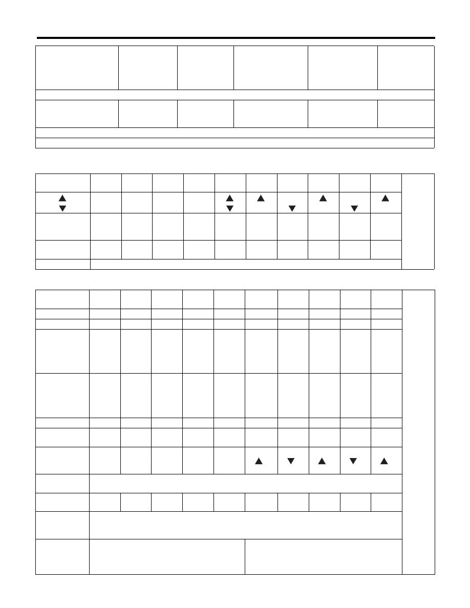
• Illuminating order table
Display Contents 1
Display Contents 2
Step 4-2. Press the trip knob: Check the beeping of SPORT shift buzzer (For AT model only, while for MT model, go to the next)
All meter indicator nee-
dle returns to lowest
position.
Light OFF
Shift display
blinks with
buzzer.
STEP 4 SS BUZZER
is displayed.
Light at the highest
brightness.
SPORT shift
buzzer beeps.
Step 5. Press the trip knob: Complete the self-diagnosis 1 cycle
All meter indicator needle returns to lowest position, and go back to step 1 after completion.
Illuminating
order
1
2
3
4
5
6
7
8
9
10
Go back
to 1 and
repeat
AT select lever
position indicator
P
R
N
D
All
lights
ON
1
2
3
4
5
Display time
(seconds)
1
0.5
0.5
0.5
1
0.5
0.5
0.5
0.5
0.5
Back-up light
White light ON
Illuminating
order
1
2
3
4
5
6
7
8
9
10
Go back
to 1 and
repeat.
Speedometer
0
0
40
60
80
100
80
60
40
0
Tachometer
0
0
1000
2000
3000
4000
3000
2000
1000
0
Fuel gauge
Lowest
position
EMPTY
Warn-
ing light
illumi-
nation
position
1/2
FULL
Highest
position
FULL
1/2
Warn-
ing light
illumi-
nation
position
EMPTY
Engine coolant
temperature
gauge
Lowest
position
C
at the
first
scale
1/2
at the
third
scale
over the
fourth
scale
(approx.
120°C)
at the
third
scale
1/2
at the
first
scale
C
ECO gauge
–Max
0
+Max
0
–Max
0
+Max
0
–Max
0
Low fuel
warning light
Light
ON
Light
ON
Light
ON
Light
OFF
Light
OFF
Light
OFF
Light
OFF
Light
OFF
Light
ON
Light
ON
AT select lever
position
indicator
P
R
N
D
All
lights
ON
1
2
3
4
5
Multi-informa-
tion display
STEP 2 is displayed.
Display time
(seconds)
2.5
2.5
2.5
2.5
2.5
2.5
2.5
2.5
2.5
2.5
Back-up light
(SS of AT
model)
White light ON
Back-up light
(Multi informa-
tion display
LCD)
White light ON
Yellow light ON
Speedometer, tachome-
ter, fuel gauge, engine
coolant temperature
gauge, ECO gauge
Microcomputer
running type
warning light,
indicator light
AT select lever
position indica-
tor light
Multi-information dis-
play
Illumination
(indicator needle,
plate, ring, LCD)
Buzzer (SPORT
shift buzzer,
VDC buzzer,
vehicle speed
warning buzzer)

IDI-10
Combination Meter System
INSTRUMENTATION/DRIVER INFO
4. SYMPTOM CHART
CAUTION:
When measuring the voltage and resistance of each control module or sensor, use a tapered pin with
a diameter of less than 0.64 mm (0.025 in) in order to avoid poor contact. Do not insert the pin more
than 2 mm (0.08 in).
Symptoms
Repair order
Reference
Combination meter assembly
does not operate.
1. Power supply
2. Ground circuit
3. Combination meter
<Ref. to IDI-11, CHECK POWER SUPPLY AND
GROUND CIRCUIT, INSPECTION, Combination
Meter System.>
Speedometer does not operate.
1. ABS C/M or VDC C/M
2. Harness
3. Combination meter
<Ref. to IDI-12, CHECK THE ABSCM OR VDCCM,
INSPECTION, Combination Meter System.>
Tachometer does not operate.
1. ECM
2. Harness
3. Combination meter
<Ref. to IDI-12, CHECK ENGINE CONTROL
MODULE (ECM), INSPECTION, Combination
Meter System.>
Fuel gauge does not operate.
1. Combination meter
2. Communication circuit
3. Harness
4. Body integrated unit
5. Fuel level sensor
<Ref. to IDI-13, CHECK FUEL LEVEL SENSOR,
INSPECTION, Combination Meter System.>
Engine coolant temperature
gauge does not operate.
1. Communication circuit
2. Engine coolant temperature sensor
3. Harness
4. Combination meter
<Ref. to IDI-15, CHECK ENGINE COOLANT TEM-
PERATURE SENSOR, INSPECTION, Combination
Meter System.>
ECO gauge does not operate.
1. Communication circuit
2. Combination meter
<Ref. to IDI-15, CHECK ECO GAUGE, INSPEC-
TION, Combination Meter System.>
NOTE:
After trip meter is reset, average fuel economy is not
displayed within 1 km and ECO gauge does not op-
erate.
Error display is shown on the odo/
trip meter.
(Except for meter with MID)
Communication circuit
<Ref. to IDI-17, COMMUNICATION ERROR DIS-
PLAY, INSPECTION, Combination Meter System.>
Error display is shown on the
Instantaneous/Average fuel econ-
omy and Estimated driving dis-
tance in the multi-information
display.
1. Communication circuit
<Ref. to LAN(diag)-2, Basic Diagnostic Proce-
dure.>
Error display is shown on the
Ambient temperature in the multi-
information display.
1. Communication circuit
2. Ambient sensor
<Ref. to LAN(diag)-2, Basic Diagnostic Proce-
dure.>
<Ref. to IDI-15, CHECK AMBIENT SENSOR,
INSPECTION, Combination Meter System.>

IDI-11
Combination Meter System
INSTRUMENTATION/DRIVER INFO
5. CHECK POWER SUPPLY AND GROUND CIRCUIT
Step
Check
Yes
No
1
CHECK POWER SUPPLY FOR COMBINA-
TION METER.
1) Remove the combination meter. <Ref. to
IDI-22, REMOVAL, Combination Meter.>
2) Disconnect the combination meter harness
connector.
3) Turn the ignition switch to ON.
4) Measure the voltage between combination
meter connector and chassis ground.
Connector & terminal
(i10) No. 3 (+) — Chassis ground (–):
Is the voltage 10 V or more?
Go to step 2.
Check the harness
for open or short
between the igni-
tion switch and
combination meter.
2
CHECK POWER SUPPLY FOR COMBINA-
TION METER.
Measure the voltage between combination
meter connector and chassis ground.
Connector & terminal
(i10) No. 1 (+) — Chassis ground (–):
Is the voltage 10 V or more?
Go to step 3.
Check the harness
for open or short
between the fuse
and combination
meter.
3
CHECK GROUND CIRCUIT OF COMBINA-
TION METER.
1) Turn the ignition switch to OFF.
2) Measure the resistance of harness between
combination meter connector and chassis
ground.
Connector & terminal
Normal meter model:
(i10) No. 11 — Chassis ground:
(i10) No. 12 — Chassis ground:
Multi information display model:
(i10) No. 11 — Chassis ground:
(i10) No. 12 — Chassis ground:
Is the resistance less than 10
:? Replace the meter
case assembly.
Repair the wiring
harness.

IDI-12
Combination Meter System
INSTRUMENTATION/DRIVER INFO
6. CHECK THE ABSCM OR VDCCM
7. CHECK ENGINE CONTROL MODULE (ECM)
Step
Check
Yes
No
1
CHECK VEHICLE SPEED SIGNAL.
1) Lift up the vehicle and support it with rigid
racks.
2) Remove the combination meter with har-
ness connector.
3) Drive the vehicle faster than 10 km/h (6 MPH).
WARNING:
Be careful not to get caught in the running
wheels.
4) Measure the voltage between combination
meter connector and chassis ground.
Connector & terminal
(i10) No. 19 (+) — Chassis ground (–):
Is the voltage less than 1 V
mo
5 V or more?
Replace the meter
case assembly.
Go to step 2.
2
CHECK HARNESS BETWEEN ABSCM OR
VDCCM AND COMBINATION METER.
1) Turn the ignition switch to OFF.
2) Disconnect the connector from ABSCM or
VDCCM and combination meter.
3) Measure the resistance between ABSCM or
VDCCM harness connector and the combina-
tion meter harness connector.
Connector & terminal
Model without VDC
(B301) No. 23 — (i10) No. 19:
Model with VDC
(B310) No. 33 — (i10) No. 19:
Is the resistance less than 10
:? Model without
VDC: Check the
ABSCM. <Ref. to
ABS(diag)-2, Basic
Diagnostic Proce-
dure.> Model with
VDC: Check the
VDCCM. <Ref. to
VDC(diag)-2,
Basic Diagnostic
Procedure.>
Repair the wiring
harness.
Step
Check
Yes
No
1
CHECK ECM SIGNAL.
1) Start the engine.
2) Measure the voltage between ECM connec-
tor and chassis ground.
Connector & terminal
(B136) No. 22 (+) — Chassis ground (–):
Is the voltage 0
mo 14 V or
more?
Go to step 2.
Inspect the ECM.
<Ref. to
EN(H4SO)(diag)-
2, Basic Diagnostic
Procedure.> <Ref.
to
EN(H4DOTC)(diag
)-2, Basic Diagnos-
tic Procedure.>
<Ref. to
EN(H6DO)(diag)-
2, Basic Diagnostic
Procedure.>
2
CHECK HARNESS BETWEEN COMBINA-
TION METER AND ECM.
1) Turn the ignition switch to OFF.
2) Disconnect the connector from ECM and
combination meter.
3) Measure the resistance between ECM har-
ness connector and combination meter harness
connector.
Connector & terminal
(B136) No. 22 — (i10) No. 20:
Is the resistance less than 10
:? Replace the meter
case assembly.
Repair the wiring
harness.
Нет комментариевНе стесняйтесь поделиться с нами вашим ценным мнением.
Текст