Subaru Legacy IV (2008 year). Service manual — part 331
EN(H4DOTC)(diag)-145
Diagnostic Procedure with Diagnostic Trouble Code (DTC)
ENGINE (DIAGNOSTICS)
AF:DTC P0139 O2 SENSOR CIRCUIT SLOW RESPONSE (BANK 1 SENSOR 2)
DTC DETECTING CONDITION:
• Two consecutive driving cycles with fault
• GENERAL DESCRIPTION <Ref. to GD(H4DOTC)-58, DTC P0139 O2 SENSOR CIRCUIT SLOW RE-
SPONSE (BANK 1 SENSOR 2), Diagnostic Trouble Code (DTC) Detecting Criteria.>
CAUTION:
After repair or replacement of faulty parts, perform Clear Memory Mode <Ref. to EN(H4DOTC)(diag)-
52, OPERATION, Clear Memory Mode.>, and Inspection Mode <Ref. to EN(H4DOTC)(diag)-43, PRO-
CEDURE, Inspection Mode.>.
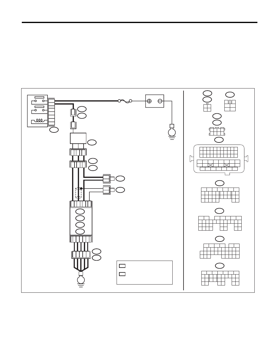
WIRING DIAGRAM:
EN-05670
B83
1 2 3 4
5 6 7 8
B138
B47
1
2
4
6
3
5
E
*
*
B138
B83
3
4
1
2
5
6
B135
B47
B19
B136
B:
C:
B137
D:
5
6
7 8
2
1
9
4
3
10
24
22 23
25
11 12 13 14 15
26 27
28
16
17 18 19 20 21
33 34
29
32
30
31
35
5
6
7
8
2
1
9
4
3
10
24
22 23
25
11 12 13 14 15
26 27
28
16 17 18 19
20 21
29 30 31
32 33
34 35
5
6
7
8
2
1
9
4
3
10
22 23
11 12 13 14 15
24 25
26
16 17
18 19 20 21
27
28 29
30 31
B19
T5
2
2
T5
B19
3
1
4
B21
1 2 3 4
12 13 14 15
5 6 7 8
16 17 18 19
9 10 11
20 21 22
23 24 25 26 27 28 29 30 31 32 33
35
34
37
36
39
38
41
40
43
42
44
45
47
46
49
48
51
50
53
52
54
T6
SBF-5
*
1
*
2
1
1
*
*
2
2
C4
B4
B30
B1
B134
T6
B134
5
6
7
8
2
1
9
4
3
10
24
22 23
25
11 12 13 14 15
26 27
28
16 17
18 19 20 21
33 34
29
32
30 31
A:
B135
B:
B136
C:
B137
D:
A:
D2
A5
D3
E2
B21
E
35
34
40
D7
36
D1
37
1 2
3 4
3
1
4
MAIN RELAY
REAR
OXYGEN SENSOR
BATTERY
ECM
: TERMINAL No. OPTIONAL
ARRANGEMENT
: TERMINAL No. OPTIONAL
ARRANGEMENT
AMONG 1, 2, 5 AND 6

EN(H4DOTC)(diag)-146
Diagnostic Procedure with Diagnostic Trouble Code (DTC)
ENGINE (DIAGNOSTICS)
Step
Check
Yes
No
1
CHECK HARNESS BETWEEN ECM AND
REAR OXYGEN SENSOR CONNECTOR.
1) Turn the ignition switch to OFF.
2) Disconnect the connectors from ECM and
rear oxygen sensor.
3) Measure the resistance of harness between
ECM and rear oxygen sensor connector.
Connector & terminal
(B135) No. 4 — (T6) No. 3:
Is the resistance less than 1
:? Go to step 2.
Repair the harness
and connector.
NOTE:
In this case, repair
the following item:
• Open circuit in
harness between
ECM and rear oxy-
gen sensor con-
nector
• Poor contact of
coupling connector
2
CHECK HARNESS BETWEEN ECM AND
REAR OXYGEN SENSOR CONNECTOR.
Measure the resistance between rear oxygen
sensor connector and chassis ground.
Connector & terminal
(T6) No. 3 — Chassis ground:
Is the resistance 1 M
: or
more?
Go to step 3.
Repair the ground
short circuit of har-
ness between
ECM and rear oxy-
gen sensor con-
nector.
3
CHECK REAR OXYGEN SENSOR.
Measure the resistance between rear oxygen
sensor terminals.
Terminals
No. 3 — No. 4
Is the resistance less than 1
:? Replace the rear
oxygen sensor.
<Ref. to
FU(H4DOTC)-48,
Rear Oxygen Sen-
sor.>
Even if DTC is
detected, the cir-
cuit has returned to
a normal condition
at this time. Repro-
duce the failure,
and then perform
the diagnosis
again.
NOTE:
In this case, tem-
porary poor con-
tact of connector
may be the cause.
EN(H4DOTC)(diag)-147
Diagnostic Procedure with Diagnostic Trouble Code (DTC)
ENGINE (DIAGNOSTICS)
AG:DTC P0140 O2 SENSOR CIRCUIT NO ACTIVITY DETECTED
(BANK1 SENSOR2)
DTC DETECTING CONDITION:
• Two consecutive driving cycles with fault
• GENERAL DESCRIPTION <Ref. to GD(H4DOTC)-63, DTC P0140 O2 SENSOR CIRCUIT NO ACTIVITY
DETECTED (BANK1 SENSOR2), Diagnostic Trouble Code (DTC) Detecting Criteria.>
CAUTION:
After repair or replacement of faulty parts, perform Clear Memory Mode <Ref. to EN(H4DOTC)(diag)-
52, OPERATION, Clear Memory Mode.>, and Inspection Mode <Ref. to EN(H4DOTC)(diag)-43, PRO-
CEDURE, Inspection Mode.>.
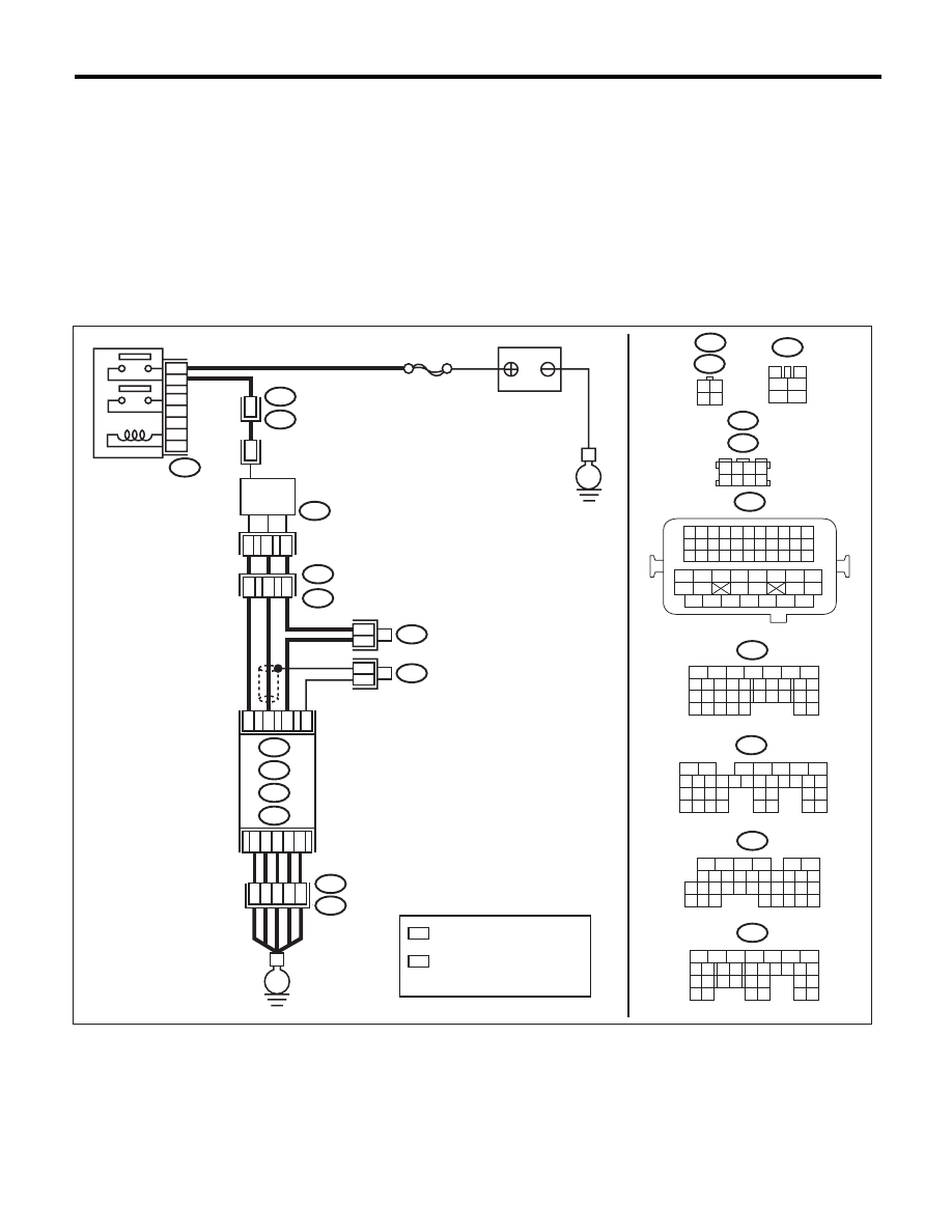
WIRING DIAGRAM:
EN-05670
B83
1 2 3 4
5 6 7 8
B138
B47
1
2
4
6
3
5
E
*
*
B138
B83
3
4
1
2
5
6
B135
B47
B19
B136
B:
C:
B137
D:
5
6
7 8
2
1
9
4
3
10
24
22 23
25
11 12 13 14 15
26 27
28
16
17 18 19 20 21
33 34
29
32
30
31
35
5
6
7
8
2
1
9
4
3
10
24
22 23
25
11 12 13 14 15
26 27
28
16 17 18 19
20 21
29 30 31
32 33
34 35
5
6
7
8
2
1
9
4
3
10
22 23
11 12 13 14 15
24 25
26
16 17
18 19 20 21
27
28 29
30 31
B19
T5
2
2
T5
B19
3
1
4
B21
1 2 3 4
12 13 14 15
5 6 7 8
16 17 18 19
9 10 11
20 21 22
23 24 25 26 27 28 29 30 31 32 33
35
34
37
36
39
38
41
40
43
42
44
45
47
46
49
48
51
50
53
52
54
T6
SBF-5
*
1
*
2
1
1
*
*
2
2
C4
B4
B30
B1
B134
T6
B134
5
6
7
8
2
1
9
4
3
10
24
22 23
25
11 12 13 14 15
26 27
28
16 17
18 19 20 21
33 34
29
32
30 31
A:
B135
B:
B136
C:
B137
D:
A:
D2
A5
D3
E2
B21
E
35
34
40
D7
36
D1
37
1 2
3 4
3
1
4
MAIN RELAY
REAR
OXYGEN SENSOR
BATTERY
ECM
: TERMINAL No. OPTIONAL
ARRANGEMENT
: TERMINAL No. OPTIONAL
ARRANGEMENT
AMONG 1, 2, 5 AND 6

EN(H4DOTC)(diag)-148
Diagnostic Procedure with Diagnostic Trouble Code (DTC)
ENGINE (DIAGNOSTICS)
Step
Check
Yes
No
1
CHECK REAR OXYGEN SENSOR DATA.
1) Warm up the engine until engine coolant
temperature is above 75°C (167°F), and keep
the engine speed at 3,000 rpm. (for up to 2 min-
utes)
2) Read the data of rear oxygen sensor signal
using Subaru Select Monitor or general scan
tool.
NOTE:
• Subaru Select Monitor
For detailed operation procedure, refer to
“READ CURRENT DATA FOR ENGINE”. <Ref.
to EN(H4DOTC)(diag)-34, Subaru Select Moni-
tor.>
• General scan tool
For detailed operation procedures, refer to the
general scan tool operation manual.
Is the voltage 490 mV or more? Go to step 6.
Go to step 2.
2
CHECK REAR OXYGEN SENSOR DATA.
1) Warm up the engine until engine coolant
temperature is above 75°C (167°F), and rapidly
reduce the engine speed from 3,000 rpm.
2) Read the data of rear oxygen sensor signal
using Subaru Select Monitor or general scan
tool.
NOTE:
• Subaru Select Monitor
For detailed operation procedure, refer to
“READ CURRENT DATA FOR ENGINE”. <Ref.
to EN(H4DOTC)(diag)-34, Subaru Select Moni-
tor.>
• General scan tool
For detailed operation procedures, refer to the
general scan tool operation manual.
Is the voltage 250 mV or less?
Go to step 6.
Go to step 3.
3
CHECK REAR OXYGEN SENSOR CONNEC-
TOR AND COUPLING CONNECTOR.
Has water entered the connec-
tor?
Completely
remove any water
inside.
Go to step 4.
4
CHECK HARNESS BETWEEN ECM AND
REAR OXYGEN SENSOR CONNECTOR.
1) Turn the ignition switch to OFF.
2) Disconnect the connectors from ECM and
rear oxygen sensor.
3) Measure the resistance of harness between
ECM and rear oxygen sensor connector.
Connector & terminal
(B135) No. 4 — (T6) No. 3:
(B135) No. 30 — (T6) No. 4:
Is the resistance less than 1
:? Go to step 5.
Repair the harness
and connector.
NOTE:
In this case, repair
the following item:
• Open circuit in
harness between
ECM and rear oxy-
gen sensor con-
nector
• Poor contact of
coupling connector
Нет комментариевНе стесняйтесь поделиться с нами вашим ценным мнением.
Текст