Subaru Legacy IV (2008 year). Service manual — part 332

EN(H4DOTC)(diag)-149
Diagnostic Procedure with Diagnostic Trouble Code (DTC)
ENGINE (DIAGNOSTICS)
AH:DTC P0171 SYSTEM TOO LEAN (BANK 1)
Refer to DTC P0172 for diagnostic procedure. <Ref. to EN(H4DOTC)(diag)-150, DTC P0172 SYSTEM TOO
RICH (BANK 1), Diagnostic Procedure with Diagnostic Trouble Code (DTC).>
5
CHECK HARNESS BETWEEN ECM AND
REAR OXYGEN SENSOR.
1) Turn the ignition switch to OFF.
2) Disconnect the connector from rear oxygen
sensor.
3) Turn the ignition switch to ON.
4) Measure the voltage between rear oxygen
sensor connector and chassis ground.
Connector & terminal
(T6) No. 3 (+) — Chassis ground (–):
Is the voltage 0.2 — 0.5 V?
Replace the rear
oxygen sensor.
<Ref. to
FU(H4DOTC)-48,
Rear Oxygen Sen-
sor.>
Repair the harness
and connector.
NOTE:
In this case, repair
the following item:
• Open circuit of
harness between
the ECM and rear
oxygen sensor
• Poor contact of
the rear oxygen
sensor connector
• Poor contact in
ECM connector
6
CHECK EXHAUST SYSTEM.
Check exhaust system parts.
NOTE:
Check the following items.
• Looseness and improper attachment of ex-
haust system parts
• Damage (crack, hole etc.) of parts
• Looseness and improper attachment of parts
between front oxygen (A/F) sensor and rear ox-
ygen sensor
Is there any fault in exhaust
system?
Repair or replace
faulty parts.
Replace the rear
oxygen sensor.
<Ref. to
FU(H4DOTC)-48,
Rear Oxygen Sen-
sor.>
Step
Check
Yes
No

EN(H4DOTC)(diag)-150
Diagnostic Procedure with Diagnostic Trouble Code (DTC)
ENGINE (DIAGNOSTICS)
AI: DTC P0172 SYSTEM TOO RICH (BANK 1)
DTC DETECTING CONDITION:
• Two consecutive driving cycles with fault
• GENERAL DESCRIPTION <Ref. to GD(H4DOTC)-66, DTC P0172 SYSTEM TOO RICH (BANK 1), Diag-
nostic Trouble Code (DTC) Detecting Criteria.>
TROUBLE SYMPTOM:
• Improper idling
• Engine stalls.
• Poor driving performance
CAUTION:
After repair or replacement of faulty parts, perform Clear Memory Mode <Ref. to EN(H4DOTC)(diag)-
52, OPERATION, Clear Memory Mode.>, and Inspection Mode <Ref. to EN(H4DOTC)(diag)-43, PRO-
CEDURE, Inspection Mode.>.
Step
Check
Yes
No
1
CHECK EXHAUST SYSTEM.
Are there holes or loose bolts
on exhaust system?
Repair the exhaust
system.
Go to step 2.
2
CHECK AIR INTAKE SYSTEM.
Are there holes, loose bolts or
disconnection of hose on air
intake system?
Repair the air
intake system.
Go to step 3.
3
CHECK FUEL PRESSURE.
WARNING:
Place “NO OPEN FLAMES” signs near the
working area.
CAUTION:
Be careful not to spill fuel.
Measure the fuel pressure while disconnecting
pressure regulator vacuum hose from intake
manifold. <Ref. to ME(H4DOTC)-25, INSPEC-
TION, Fuel Pressure.>
CAUTION:
Release fuel pressure before removing the
fuel pressure gauge.
NOTE:
If fuel pressure does not increase, squeeze the
fuel return hose 2 to 3 times, then measure fuel
pressure again.
Is the measured value 284 —
314 kPa (2.9 — 3.2 kg/cm
2
,
41 — 46 psi)?
Go to step 4.
Repair the follow-
ing item.
Fuel pressure is
too high:
• Clogged fuel
return line or bent
hose
Fuel pressure is
too low:
• Improper fuel
pump discharge
• Clogged fuel
supply line
4
CHECK FUEL PRESSURE.
After connecting the pressure regulator vacuum
hose, measure fuel pressure. <Ref. to
ME(H4DOTC)-25, INSPECTION, Fuel Pres-
sure.>
CAUTION:
Release fuel pressure before removing the
fuel pressure gauge.
NOTE:
• If fuel pressure does not increase, squeeze
fuel return hose 2 to 3 times, then measure fuel
pressure again.
• If the measured value at this step is out of
specification, check or replace pressure regula-
tor and pressure regulator vacuum hose.
Is the measured value 230 —
260 kPa (2.35 — 2.65 kg/cm
2
,
33 — 38 psi)?
Go to step 5.
Repair the follow-
ing item.
Fuel pressure is
too high:
• Faulty pressure
regulator
• Clogged fuel
return line or bent
hose
Fuel pressure is
too low:
• Faulty pressure
regulator
• Improper fuel
pump discharge
• Clogged fuel
supply line

EN(H4DOTC)(diag)-151
Diagnostic Procedure with Diagnostic Trouble Code (DTC)
ENGINE (DIAGNOSTICS)
5
CHECK ENGINE COOLANT TEMPERATURE
SENSOR.
1) Start the engine and warm up completely.
2) Read the data of engine coolant tempera-
ture sensor signal using Subaru Select Monitor
or general scan tool.
NOTE:
• Subaru Select Monitor
For detailed operation procedure, refer to
“READ CURRENT DATA FOR ENGINE”. <Ref.
to EN(H4DOTC)(diag)-34, Subaru Select Moni-
tor.>
• General scan tool
For detailed operation procedures, refer to the
general scan tool operation manual.
Is the engine coolant tempera-
ture 75°C (167°F) or higher?
Go to step 6.
Replace the
engine coolant
temperature sen-
sor. <Ref. to
FU(H4DOTC)-31,
Engine Coolant
Temperature Sen-
sor.>
6
CHECK MASS AIR FLOW AND INTAKE AIR
TEMPERATURE SENSOR.
1) Start the engine and warm up engine until
coolant temperature is higher than 75°C (167°F).
2) For AT models, set the select lever to “P”
range or “N” range, and for MT models, place
the shift lever in the neutral position.
3) Turn the A/C switch to OFF.
4) Turn all the accessory switches to OFF.
5) Read the data of the mass air flow and
intake air temperature sensor signal using Sub-
aru Select Monitor or general scan tool.
NOTE:
• Subaru Select Monitor
For detailed operation procedure, refer to
“READ CURRENT DATA FOR ENGINE”. <Ref.
to EN(H4DOTC)(diag)-34, Subaru Select Moni-
tor.>
• General scan tool
For detailed operation procedures, refer to the
general scan tool operation manual.
Is the measured value 2.0 —
5.0 g/s (0.26 — 0.66 lb/m)?
Go to step 7.
Replace the mass
air flow and intake
air temperature
sensor. <Ref. to
FU(H4DOTC)-36,
Mass Air Flow and
Intake Air Temper-
ature Sensor.>
7
CHECK MASS AIR FLOW AND INTAKE AIR
TEMPERATURE SENSOR.
1) Start the engine and warm up engine until
coolant temperature is higher than 75°C (167°F).
2) For AT models, set the select lever to “P”
range or “N” range, and for MT models, place
the shift lever in the neutral position.
3) Turn the A/C switch to OFF.
4) Turn all the accessory switches to OFF.
5) Open the front hood.
6) Measure the ambient temperature.
7) Read the data of the mass air flow and
intake air temperature sensor signal using Sub-
aru Select Monitor or general scan tool.
NOTE:
• Subaru Select Monitor
For detailed operation procedure, refer to
“READ CURRENT DATA FOR ENGINE”. <Ref.
to EN(H4DOTC)(diag)-34, Subaru Select Moni-
tor.>
• General scan tool
For detailed operation procedures, refer to the
general scan tool operation manual.
Subtract ambient temperature
from intake air temperature. Is
the obtained value –10 — 50°C
(–18 — 90°F)?
Repair the poor
contact of ECM
connector.
Check the mass air
flow and intake air
temperature sen-
sor.
<Ref. to
FU(H4DOTC)-36,
Mass Air Flow and
Intake Air Temper-
ature Sensor.>
Step
Check
Yes
No
EN(H4DOTC)(diag)-152
Diagnostic Procedure with Diagnostic Trouble Code (DTC)
ENGINE (DIAGNOSTICS)
AJ:DTC P0181 FUEL TEMPERATURE SENSOR “A” CIRCUIT RANGE/
PERFORMANCE
DTC DETECTING CONDITION:
• Two consecutive driving cycles with fault
• GENERAL DESCRIPTION <Ref. to GD(H4DOTC)-67, DTC P0181 FUEL TEMPERATURE SENSOR “A”
CIRCUIT RANGE/PERFORMANCE, Diagnostic Trouble Code (DTC) Detecting Criteria.>
CAUTION:
After repair or replacement of faulty parts, perform Clear Memory Mode <Ref. to EN(H4DOTC)(diag)-
52, OPERATION, Clear Memory Mode.>, and Inspection Mode <Ref. to EN(H4DOTC)(diag)-43, PRO-
CEDURE, Inspection Mode.>.
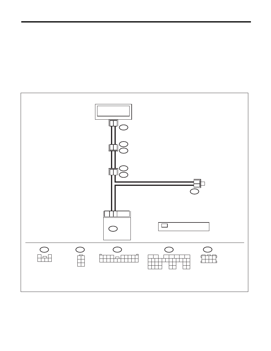
WIRING DIAGRAM:
EN-03923
B83
30
17
ECM
B135
R58
R67
R46
R1
B97
B97
R67
R58
B135
2
3
1
4
4
18
B83
FUEL TEMPERATURE
SENSOR
FUEL TANK
1
2
3 4 5 6
1 2
3 4
5 6
1 2 3 4
5 6 7 8 9
10 11 12 13 14 15 16 17 18 19 20
3 4
5 6
1 2
7 8
:TERMINAL No. OPTIONAL
ARRANGEMENT
*
*
*
5
6
7
8
2
1
9
4
3
10
24
22 23
25
11 12 13 14 15
26 27
28
16 17 18 19
20 21
29 30 31
32 33
34 35
Нет комментариевНе стесняйтесь поделиться с нами вашим ценным мнением.
Текст