Subaru Legacy IV (2008 year). Service manual — part 147

EN(H4SO)(diag)-191
Diagnostic Procedure with Diagnostic Trouble Code (DTC)
ENGINE (DIAGNOSTICS)
Step
Check
Yes
No
1
CHECK HARNESS BETWEEN ECM AND
CAMSHAFT POSITION SENSOR.
1) Turn the ignition switch to OFF.
2) Disconnect the connector from ECM and
camshaft position sensor.
3) Measure the resistance of harness between
ECM and camshaft position sensor connector.
Connector & terminal
(B134) No. 12 — (E15) No. 1:
(B134) No. 22 — (E15) No. 2:
Is the resistance less than 1
:? Go to step 2.
Repair the harness
and connector.
NOTE:
In this case, repair
the following item:
• Open circuit in
harness between
the ECM and cam-
shaft position sen-
sor connector
• Poor contact in
ECM connector
• Poor contact of
coupling connector
2
CHECK HARNESS BETWEEN ECM AND
CAMSHAFT POSITION SENSOR.
Measure the resistance between camshaft
position sensor connector and engine ground.
Connector & terminal
(E15) No. 1 — Engine ground:
Is the resistance 1 M
: or
more?
Go to step 3.
Repair the short
circuit to ground in
harness between
ECM and camshaft
position sensor.
NOTE:
The harness be-
tween both con-
nectors are
shielded. Remove
the shield and re-
pair the ground
short circuit of the
harness circuit.
3
CHECK INSTALLATION CONDITION OF
CAMSHAFT POSITION SENSOR.
Is the camshaft position sensor
installation bolt tightened
securely?
Go to step 4.
Tighten the cam-
shaft position sen-
sor installation bolt
securely.
4
CHECK CAMSHAFT POSITION SENSOR.
1) Remove the camshaft position sensor.
2) Measure the resistance between connector
terminals of camshaft position sensor.
Terminals
No. 1 — No. 2:
Is the resistance between 1 and
4 k
:?
Go to step 5.
Replace the cam-
shaft position sen-
sor. <Ref. to
FU(H4SO)-24,
Camshaft Position
Sensor.>
5
CHECK CAM SPROCKET.
Remove the timing belt cover. <Ref. to
ME(H4SO)-43, Timing Belt Cover.>
Are cam sprocket teeth cracked
or damaged?
Replace the cam
sprocket. <Ref. to
ME(H4SO)-49,
Cam Sprocket.>
Go to step 6.
6
CHECK INSTALLATION CONDITION OF
TIMING BELT.
Turn the crankshaft using ST, and align align-
ment mark on cam sprocket with alignment
mark on timing belt cover LH.
ST
499987500
CRANKSHAFT
SOCKET
Is the timing belt dislocated
from its proper position?
Repair the installa-
tion condition of
timing belt. <Ref. to
ME(H4SO)-44,
Timing Belt.>
Replace the cam-
shaft position sen-
sor. <Ref. to
FU(H4SO)-24,
Camshaft Position
Sensor.>
EN(H4SO)(diag)-192
Diagnostic Procedure with Diagnostic Trouble Code (DTC)
ENGINE (DIAGNOSTICS)
BD:DTC P0400 EXHAUST GAS RECIRCULATION FLOW
DTC DETECTING CONDITION:
• Two consecutive driving cycles with fault
• GENERAL DESCRIPTION <Ref. to GD(H4SO)-96, DTC P0400 EXHAUST GAS RECIRCULATION
FLOW, Diagnostic Trouble Code (DTC) Detecting Criteria.>
TROUBLE SYMPTOM:
• Movement performance problem when engine is low speed.
• Improper idling
• Movement performance problem
CAUTION:
After repair or replacement of faulty parts, perform Clear Memory Mode <Ref. to EN(H4SO)(diag)-50,
OPERATION, Clear Memory Mode.>, and Inspection Mode <Ref. to EN(H4SO)(diag)-41, PROCEDURE,
Inspection Mode.>.
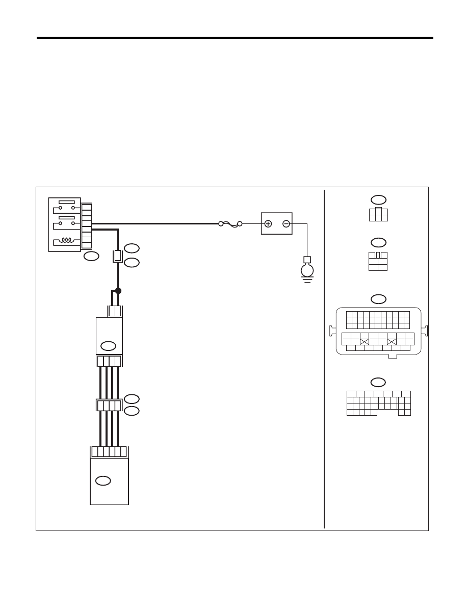
WIRING DIAGRAM:
EN-06839
E
B47
E18
2
5
6
4
3
1
B21
E2
E2
B21
5
3
6
4
2
1
48
30
25
29
26
SBF-7
B134
ECM
B47
E18
3
4
1
2
5
6
1
3
4 5 6
2
MAIN RELAY
BATTERY
EGR
VALVE
B134
8
5
6
10 11 12 13 14 15
7
2
1
3
4
16
30
19 20
22
28 29
9
17
18
25
21
23 24
32
31
26 27
33 34
B21
1 2 3 4
12 13 14 15
5 6 7 8
16 17 18 19
9 10 11
20 21 22
23 24 25 26 27 28 29 30 31 32 33
35
34
37
36
39
38
41
40
43
42
44
45
47
46
49
48
51
50
53
52
54
20
10
8
9

EN(H4SO)(diag)-193
Diagnostic Procedure with Diagnostic Trouble Code (DTC)
ENGINE (DIAGNOSTICS)
Step
Check
Yes
No
1
CHECK CURRENT DATA.
1) Start the engine.
2) Read data of intake manifold absolute pres-
sure signal using Subaru Select Monitor or gen-
eral scan tool.
NOTE:
• SUBARU SELECT MONITOR
For detailed operation procedure, refer to
“READ CURRENT DATA FOR ENGINE”. <Ref.
to EN(H4SO)(diag)-33, Subaru Select Moni-
tor.>
• General Scan Tool
For detailed operation procedures, refer to the
general scan tool operation manual.
Is the measured value 53.3 kPa
(400 mmHg, 15.75 inHg) or
more?
Make sure that the
EGR valve, mani-
fold absolute pres-
sure sensor and
throttle body are
installed securely.
Go to step 2.
2
CHECK EGR VALVE.
Remove the EGR valve.
Are there holes, plugged piping
or foreign objects caught in the
EGR system?
Repair the EGR
system.
Replace the EGR
valve. <Ref. to
FU(H4SO)-29,
EGR Valve.>
EN(H4SO)(diag)-194
Diagnostic Procedure with Diagnostic Trouble Code (DTC)
ENGINE (DIAGNOSTICS)
BE:DTC P0420 CATALYST SYSTEM EFFICIENCY BELOW THRESHOLD (BANK 1)
DTC DETECTING CONDITION:
• Two consecutive driving cycles with fault
• GENERAL DESCRIPTION <Ref. to GD(H4SO)-99, DTC P0420 CATALYST SYSTEM EFFICIENCY BE-
LOW THRESHOLD (BANK 1), Diagnostic Trouble Code (DTC) Detecting Criteria.>
TROUBLE SYMPTOM:
• Engine stalls.
• Idle mixture is out of specifications.
CAUTION:
After repair or replacement of faulty parts, perform Clear Memory Mode <Ref. to EN(H4SO)(diag)-50,
OPERATION, Clear Memory Mode.>, and Inspection Mode <Ref. to EN(H4SO)(diag)-41, PROCEDURE,
Inspection Mode.>.
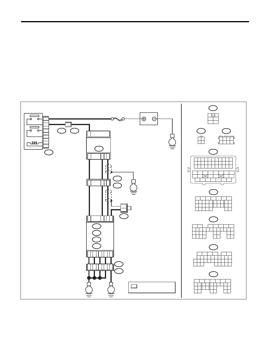
WIRING DIAGRAM:
EN-06836
A5
D1
D2
D3
D7
36
34
35
37
52
ECM
B21
B138
E2
B135
B:
D: B137
C: B136
E
E
A: B134
B137
5
6
7
8
2
1
9
4
3
10
22 23
11 12 13 14 15
24 25
26
16 17
18 19 20 21
27
28 29
30 31
B134
5
6
7
8
2
1
9
4
3
10
24
22 23
25
11 12 13 14 15
26 27
28
16 17
18 19 20 21
33 34
29
32
30 31
B136
5
6
7 8
2
1
9
4
3
10
24
22 23
25
11 12 13 14 15
26 27
28
16
17 18 19 20 21
33 34
29
32
30
31
35
B135
5
6
7
8
2
1
9
4
3
10
24
22 23
25
11 12 13 14 15
26 27
28
16 17 18 19
20 21
29 30 31
32 33
34 35
A:
B:
C:
D:
*
*
3
4
1
2
5
6
B327
SBF-5
E
B327
E23
6
4
5
3
2
1
1
B21
E2
50
53
1
19
E2
B21
E
E23
BATTERY
REAR OXYGEN
SENSOR
A/F, OXYGEN
SENSOR RELAY
1
3 4
2
2
3
4
B1
B4
A29
C4
B138
3 4
5 6
1 2
7 8
B21
1 2 3 4 5 6 7 8 9 10 11
12 13 14 15 16 17 18 19 20 21 22
23 24 25 26 27 28 29 30 31 32 33
34
35
42
43
36
37
38
39
48
49
50
51
52
53
54
40
41
44
45
46
47
: TERMINAL No. OPTIONAL
ARRANGEMENT
*
Нет комментариевНе стесняйтесь поделиться с нами вашим ценным мнением.
Текст