Subaru Legacy IV (2008 year). Service manual — part 145

EN(H4SO)(diag)-183
Diagnostic Procedure with Diagnostic Trouble Code (DTC)
ENGINE (DIAGNOSTICS)
Step
Check
Yes
No
1
CHECK HARNESS BETWEEN ECM AND
KNOCK SENSOR.
1) Turn the ignition switch to OFF.
2) Disconnect the connectors from ECM.
3) Measure the resistance between ECM con-
nectors.
Connector & terminal
(B134) No. 15 — (B134) No. 29:
Is the resistance less than
500 k
:?
Go to step 2.
Go to step 3.
2
CHECK KNOCK SENSOR.
1) Disconnect the connector from knock sen-
sor.
2) Measure the resistance between knock
sensor terminals.
Terminals
No. 1 — No. 2:
Is the resistance less than
500 k
:?
Replace the knock
sensor. <Ref. to
FU(H4SO)-25,
Knock Sensor.>
Repair the short
circuit to ground in
harness between
ECM and knock
sensor connector.
NOTE:
The harness be-
tween both con-
nectors are
shielded. Remove
the shield and re-
pair the short cir-
cuit of harness.
3
CHECK INPUT SIGNAL OF ECM.
1) Connect the connector to ECM.
2) Turn the ignition switch to ON.
3) Measure the voltage between ECM and
chassis ground.
Connector & terminal
(B134) No. 15 (+) — Chassis ground (–):
Is the voltage 2 V or more?
Even if DTC is
detected, the cir-
cuit has returned to
a normal condition
at this time. Repro-
duce the failure,
and then perform
the diagnosis
again.
NOTE:
In this case, tem-
porary poor con-
tact of connector
may be the cause.
Repair the poor
contact of ECM
connector.
EN(H4SO)(diag)-184
Diagnostic Procedure with Diagnostic Trouble Code (DTC)
ENGINE (DIAGNOSTICS)
AZ:DTC P0335 CRANKSHAFT POSITION SENSOR “A” CIRCUIT
DTC DETECTING CONDITION:
• Immediately at fault recognition
• GENERAL DESCRIPTION <Ref. to GD(H4SO)-88, DTC P0335 CRANKSHAFT POSITION SENSOR “A”
CIRCUIT, Diagnostic Trouble Code (DTC) Detecting Criteria.>
TROUBLE SYMPTOM:
• Engine stalls.
• Failure of engine to start
CAUTION:
After repair or replacement of faulty parts, perform Clear Memory Mode <Ref. to EN(H4SO)(diag)-50,
OPERATION, Clear Memory Mode.>, and Inspection Mode <Ref. to EN(H4SO)(diag)-41, PROCEDURE,
Inspection Mode.>.
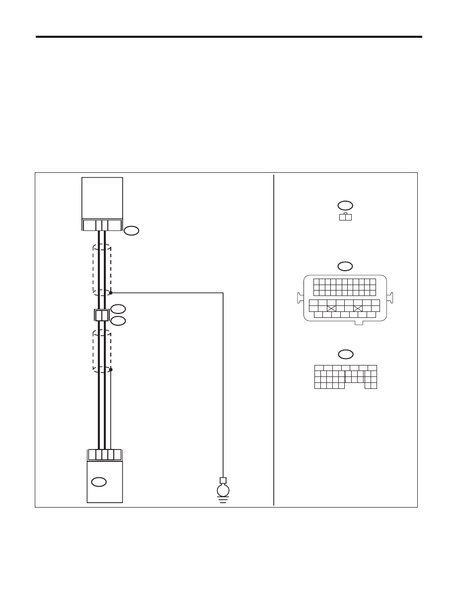
WIRING DIAGRAM:
EN-04039
B134
5
6
7
8
2
1
9
4
3
10
24
22 23
25
11 12 13 14 15
26 27
28
16 17
18 19 20 21
33 34
29
32
30 31
1
2
15
14
14
24
B21
E2
E10
E10
1 2
B134 ECM
13
E
CRANKSHAFT
POSITION
SENSOR
B21
1 2 3 4
12 13 14 15
5 6 7 8
16 17 18 19
9 10 11
20 21 22
23 24 25 26 27 28 29 30 31 32 33
35
34
37
36
39
38
41
40
43
42
44
45
47
46
49
48
51
50
53
52
54

EN(H4SO)(diag)-185
Diagnostic Procedure with Diagnostic Trouble Code (DTC)
ENGINE (DIAGNOSTICS)
Step
Check
Yes
No
1
CHECK INSTALLATION CONDITION OF
CRANKSHAFT POSITION SENSOR.
Is the crankshaft position sen-
sor installation bolt tightened
securely?
Go to step 2.
Tighten the crank-
shaft position sen-
sor installation bolt
securely.
2
CHECK CRANKSHAFT POSITION SENSOR.
1) Turn the ignition switch to OFF.
2) Remove the crankshaft position sensor.
3) Measure the resistance between connector
terminals of crankshaft position sensor.
Terminals
No. 1 — No. 2:
Is the resistance between 1 and
4 k
:?
Go to step 3.
Replace the crank-
shaft position sen-
sor. <Ref. to
FU(H4SO)-23,
Crankshaft Posi-
tion Sensor.>
3
CHECK HARNESS BETWEEN ECM AND
CRANK SHAFT POSITION SENSOR.
1) Disconnect the connectors from ECM.
2) Measure the resistance of harness between
ECM and crankshaft position sensor connector.
Connector & terminal
(B134) No. 13 — (E10) No. 1:
(B134) No. 14 — (E10) No. 2:
Is the resistance less than 1
:? Repair the poor
contact of ECM
and crankshaft
position sensor
connector.
Repair the harness
and connector.
NOTE:
In this case, repair
the following item:
• Open circuit in
harness between
ECM and crank-
shaft position sen-
sor connector
• Poor contact of
coupling connector
EN(H4SO)(diag)-186
Diagnostic Procedure with Diagnostic Trouble Code (DTC)
ENGINE (DIAGNOSTICS)
BA:DTC P0336 CRANKSHAFT POSITION SENSOR “A” CIRCUIT RANGE/
PERFORMANCE
DTC DETECTING CONDITION:
• Two consecutive driving cycles with fault
• GENERAL DESCRIPTION <Ref. to GD(H4SO)-90, DTC P0336 CRANKSHAFT POSITION SENSOR “A”
CIRCUIT RANGE/PERFORMANCE, Diagnostic Trouble Code (DTC) Detecting Criteria.>
TROUBLE SYMPTOM:
• Engine stalls.
• Failure of engine to start
CAUTION:
After repair or replacement of faulty parts, perform Clear Memory Mode <Ref. to EN(H4SO)(diag)-50,
OPERATION, Clear Memory Mode.>, and Inspection Mode <Ref. to EN(H4SO)(diag)-41, PROCEDURE,
Inspection Mode.>.
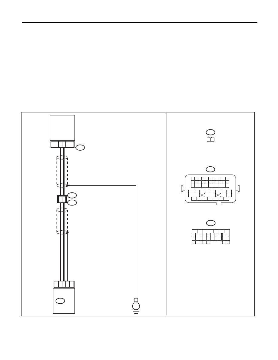
WIRING DIAGRAM:
EN-04039
B134
5
6
7
8
2
1
9
4
3
10
24
22 23
25
11 12 13 14 15
26 27
28
16 17
18 19 20 21
33 34
29
32
30 31
1
2
15
14
14
24
B21
E2
E10
E10
1 2
B134 ECM
13
E
CRANKSHAFT
POSITION
SENSOR
B21
1 2 3 4
12 13 14 15
5 6 7 8
16 17 18 19
9 10 11
20 21 22
23 24 25 26 27 28 29 30 31 32 33
35
34
37
36
39
38
41
40
43
42
44
45
47
46
49
48
51
50
53
52
54
Нет комментариевНе стесняйтесь поделиться с нами вашим ценным мнением.
Текст