Subaru Legacy IV (2008 year). Service manual — part 252
IN(H4DOTC)-5
General Description
INTAKE (INDUCTION)
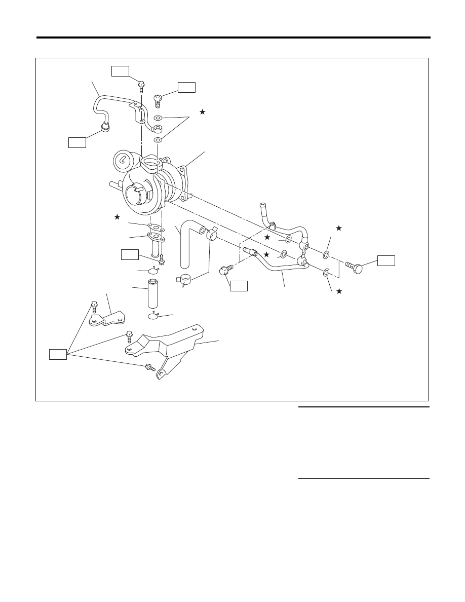
4. TURBOCHARGER
(1)
Oil inlet pipe
(8)
Oil outlet pipe
Tightening torque:N·m (kgf-m, ft-lb)
(2)
Metal gasket
(9)
Clip
T1: 5 (0.5, 3.7)
(3)
Turbocharger
(10)
Oil outlet hose
T2: 7.8 (0.8, 5.8)
(4)
Water pipe
(11)
Turbocharger bracket RH
T3: 16 (1.6, 11.8)
(5)
Clip
(12)
Turbocharger bracket LH
T4: 20 (2.0, 14.8)
(6)
Engine coolant hose
T5: 23 (2.3, 17.0)
(7)
Gasket
T6: 33 (3.4, 24.3)
IN-02443
T3
T2
(3)
(8)
(4)
(5)
(9)
(9)
(6)
(12)
(2)
(2)
(2)
(7)
(2)
(11)
(10)
T6
T1
T4
T5
(1)
(2)
T2
IN(H4DOTC)-6
General Description
INTAKE (INDUCTION)
B: CAUTION
• Wear appropriate work clothing, including a cap,
protective goggles and protective shoes when per-
forming any work.
• Remove contamination including dirt and corro-
sion before removal, installation or disassembly.
• Keep the disassembled parts in order and pro-
tect them from dust and dirt.
• Before removal, installation or disassembly, be
sure to clarify the failure. Avoid unnecessary re-
moval, installation, disassembly and replacement.
• Vehicle components are extremely hot after driv-
ing. Be wary of receiving burns from heated parts.
• Be sure to tighten fasteners including bolts and
nuts to the specified torque.
• Place shop jacks or rigid racks at the specified
points.
• Before disconnecting connectors of sensors or
units, be sure to disconnect the ground cable from
the battery.
IN(H4DOTC)-7
Air Cleaner Element
INTAKE (INDUCTION)
2. Air Cleaner Element
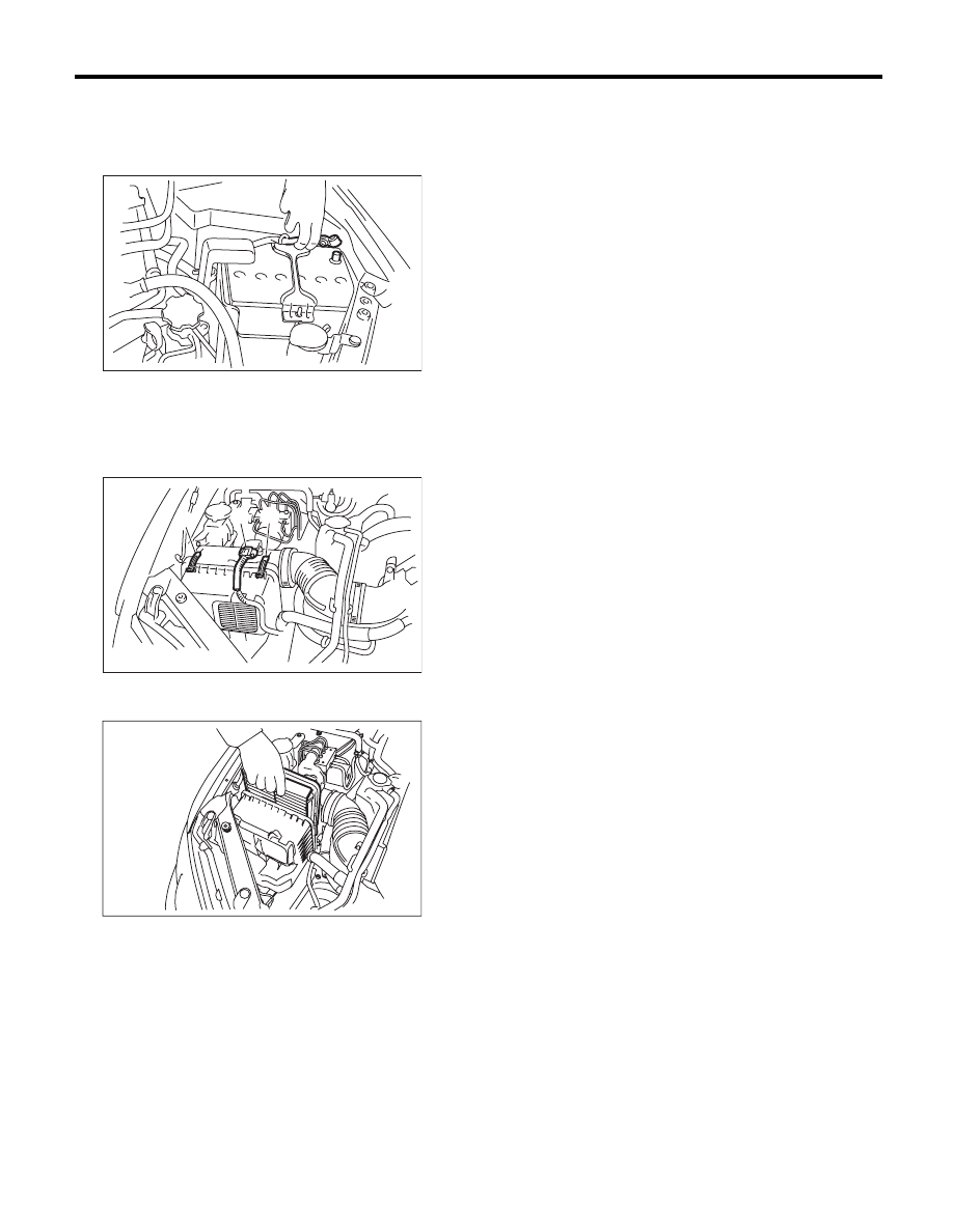
A: REMOVAL
1) Disconnect the ground cable from battery.
2) Remove the air intake duct. <Ref. to
IN(H4DOTC)-9, REMOVAL, Air Intake Duct.>
3) Disconnect the connector (A) from mass air flow
and intake air temperature sensor.
4) Remove the clip (B) from the air cleaner case.
5) Open the air cleaner case, and remove the air
cleaner element.
B: INSTALLATION
Install in the reverse order of removal.
CAUTION:
Be sure to use SUBARU genuine air cleaner el-
ement depending on the engine type when re-
placing the air cleaner elements. Using other air
cleaner element may affect the engine perfor-
mance.
NOTE:
Check that there are no foreign objects in the air
cleaner case.
C: INSPECTION
Replace if excessively damaged or dirty.
IN-00203
(A)
(B)
(B)
IN-02254
IN-02255
IN(H4DOTC)-8
Air Cleaner Case
INTAKE (INDUCTION)
3. Air Cleaner Case
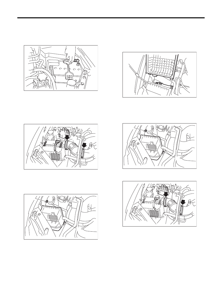
A: REMOVAL
1) Remove the collector cover.
2) Disconnect the ground cable from battery.
3) Remove the air intake duct. <Ref. to
IN(H4DOTC)-9, REMOVAL, Air Intake Duct.>
4) Disconnect the connector (A) from mass air flow
and intake air temperature sensor.
5) Loosen the clamp (B) which connects the air in-
take boot and intake duct.
6) Remove the clip (C) from the air cleaner case.
7) Remove the air cleaner case (rear) and air in-
take boot.
8) Remove the air cleaner element.
9) Remove the bolts (A) and nuts (B) which secure
the air cleaner case (front) to the body.
10) Remove the air cleaner case (front).
B: INSTALLATION
Install in the reverse order of removal.
NOTE:
When installing the air cleaner case (rear), align the
protrusion of the air cleaner case (rear) to the hole
on the air cleaner case (front) to install.
Tightening torque:
Bolt (A)
6 N·m (0.6 kgf-m, 4.4 ft-lb)
Nut (B)
7.5 N·m (0.8 kgf-m, 5.5 ft-lb)
Tightening torque:
2.5 N·m (0.3 kgf-m, 1.8 ft-lb)
C: INSPECTION
Check for cracks or loose connections.
IN-00203
(A)
(B)
(C)
(C)
(B)
IN-02210
(B)
(A)
IN-02211
IN-00220
(B)
(A)
IN-02211
IN-02491
Нет комментариевНе стесняйтесь поделиться с нами вашим ценным мнением.
Текст