Subaru Legacy IV (2008 year). Service manual — part 250
EC(H4DOTC)-20
PCV Hose Assembly
EMISSION CONTROL (AUX. EMISSION CONTROL DEVICES)
14.PCV Hose Assembly
A: REMOVAL
CAUTION:
Do not remove unless the PCV hose, diagnos-
tics connector and PCV valve are damaged.
1) Remove the collector cover.
2) Remove the intake manifold. <Ref. to
FU(H4DOTC)-16, REMOVAL, Intake Manifold.>
3) Remove the secondary air combination valve
RH. <Ref. to EC(H4DOTC)-22, SECONDARY AIR
COMBINATION VALVE RH, REMOVAL, Second-
ary Air Combination Valve.>
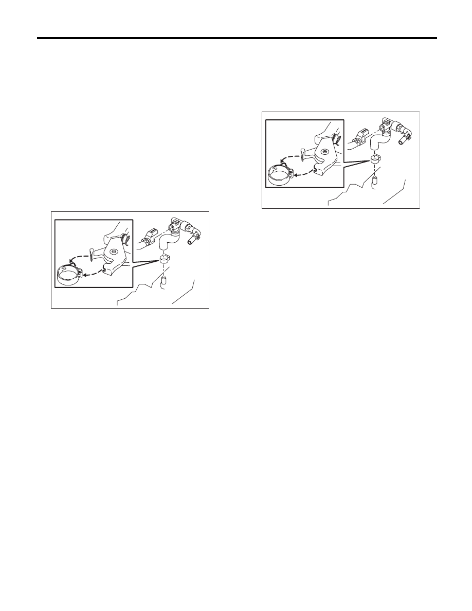
4) Fit the depression in the ST with the protrusion
on the clamp to unlock.
5) Remove the PCV hose assembly.
ST
18353AA000
CLAMP PLIER
B: INSTALLATION
1) Install the PCV hose assembly, then lock by fit-
ting the ST on the clamp protrusion.
NOTE:
Use a new clamp.
ST
18353AA000
CLAMP PLIER
2) Install the secondary air combination valve RH.
<Ref. to EC(H4DOTC)-23, SECONDARY AIR
COMBINATION VALVE RH, INSTALLATION, Sec-
ondary Air Combination Valve.>
3) Install the intake manifold.
<Ref. to FU(H4DOTC)-20, INSTALLATION, Intake
Manifold.>
4) Install the collector cover.
EC-02388
EC-02388
EC(H4DOTC)-21
Secondary Air Pump
EMISSION CONTROL (AUX. EMISSION CONTROL DEVICES)
15.Secondary Air Pump
A: REMOVAL
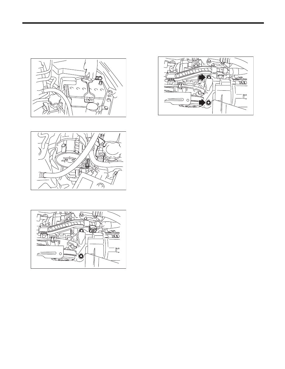
1) Remove the collector cover.
2) Disconnect the ground cable from battery.
3) Disconnect the connector (A) and air duct (B)
from secondary air pump.
4) Remove the clip (A) which holds the harness on
the harness stay and remove the bolts (B) which
holds the secondary air pump on the vehicle.
5) Remove the secondary air pump.
B: INSTALLATION
Install in the reverse order of removal.
Tightening torque:
19 N·m (1.9 kgf-m, 14.0 ft-lb)
C: INSPECTION
Make sure the hoses are not cracked or loose.
IN-00203
EC-02193
(A)
(B)
EC-02404
(A)
(B)
EC-02370
EC(H4DOTC)-22
Secondary Air Combination Valve
EMISSION CONTROL (AUX. EMISSION CONTROL DEVICES)
16.Secondary Air Combination
Valve
A: REMOVAL
1. SECONDARY AIR COMBINATION
VALVE LH
1) Remove the collector cover.
2) Disconnect the ground cable from battery.
3) Remove the intercooler. <Ref. to IN(H4DOTC)-
12, REMOVAL, Intercooler.>
4) Disconnect the connector from the secondary air
combination valve LH.
5) Disconnect the air duct A.
6) Remove the secondary air pipe LH.
7) Remove the secondary air combination valve
LH.
2. SECONDARY AIR COMBINATION
VALVE RH
1) Remove the collector cover.
2) Disconnect the ground cable from battery.
3) Remove the intercooler. <Ref. to IN(H4DOTC)-
12, REMOVAL, Intercooler.>
4) Remove the intake manifold. <Ref. to
FU(H4DOTC)-16, REMOVAL, Intake Manifold.>
5) Disconnect the air duct A.
6) Remove the secondary air pipe RH.
7) Remove the secondary air combination valve
RH.
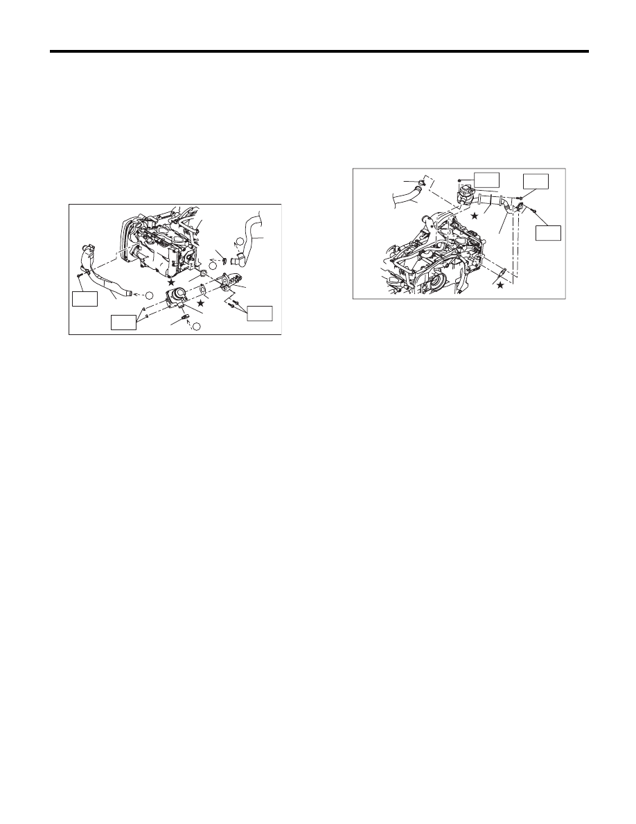
(A) Secondary air combination valve LH
(B) Clamp
(C) Air duct A
(D) Gasket
(E) Air duct B
(F) Secondary air pipe LH
(G) Gasket
IN-00203
EC-02407
(A)
(D)
(F)
(B)
(B)
(E)
a
a
(G)
(C)
b
b
(A) Secondary air combination valve RH
(B) Clamp
(C) Air duct A
(D) Gasket
(E) Secondary air pipe RH
(F) Gasket
IN-00203
EC-02213
(B)
(C)
(E)
(F)
(D)
(A)
EC(H4DOTC)-23
Secondary Air Combination Valve
EMISSION CONTROL (AUX. EMISSION CONTROL DEVICES)
B: INSTALLATION
1. SECONDARY AIR COMBINATION
VALVE LH
Install in the reverse order of removal.
NOTE:
Use a new gasket.
Tightening torque:
T1: 9 N·m (0.9 kgf-m, 6.6 ft-lb)
T2: 19 N·m (1.9 kgf-m, 14.0 ft-lb)
2. SECONDARY AIR COMBINATION
VALVE RH
Install in the reverse order of removal.
NOTE:
Use a new gasket.
Tightening torque:
T: 9 N·m (0.9 kgf-m, 6.6 ft-lb)
C: INSPECTION
Check the air duct and pipe for looseness.
(A) Secondary air combination valve LH
(B) Clamp
(C) Air duct A
(D) Gasket
(E) Air duct B
(F) Secondary air pipe LH
(G) Gasket
EC-02390
(A)
(D)
(F)
(B)
(B)
(E)
T1
T2
a
a
T1
(G)
(C)
b
b
(A) Secondary air combination valve RH
(B) Clamp
(C) Air duct A
(D) Gasket
(E) Secondary air pipe RH
(F) Gasket
EC-02425
(B)
(C)
(E)
(F)
(D)
(A)
T
T
T
Нет комментариевНе стесняйтесь поделиться с нами вашим ценным мнением.
Текст