Subaru Legacy IV (2008 year). Service manual — part 114
EN(H4SO)(diag)-59
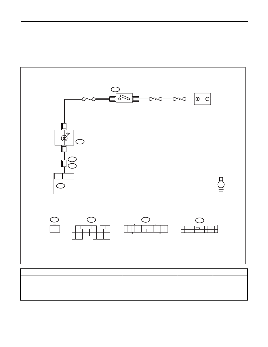
Malfunction Indicator Light
ENGINE (DIAGNOSTICS)
D: MALFUNCTION INDICATOR LIGHT DOES NOT GO OFF
DIAGNOSIS:
The malfunction indicator light circuit is shorted.
TROUBLE SYMPTOM:
Although malfunction indicator light comes on when the engine runs, DTC is not shown on the Subaru Select
Monitor display.
WIRING DIAGRAM:
Step
Check
Yes
No
1
CHECK HARNESS BETWEEN ECM AND
COMBINATION METER CONNECTOR.
1) Turn the ignition switch to OFF.
2) Disconnect the connectors from ECM.
3) Turn the ignition switch to ON.
Does the malfunction indicator
light illuminate?
Repair the short
circuit of harness
between ECM and
combination meter
connector.
Replace the ECM.
<Ref. to
FU(H4SO)-39,
Engine Control
Module (ECM).>
EN-05697
3
B72
i3
B38
B136
i10
SBF-6
1
11
3
B72
8
MAIN SBF
No.5
16
E
1
3
4 5 6
2
B136
i10
B38
1 2 3 4
5 6 7 8 9
10 11 12 13 14 15 16 17 18 19 20
2
1
3 4
6 7 8 9 10
22
21
20
19
18
17
16
15
14
13
12
11
5
16
10 11 12 13 14 15
25
24
30
9
8
7
17 18 19 20
28
21 22 23
29
32
31
1
2
3
4
5
6
27
26
33 34 35
ECM
COMBINATION
METER
IGNITION
SWITCH
BATTERY
EN(H4SO)(diag)-60
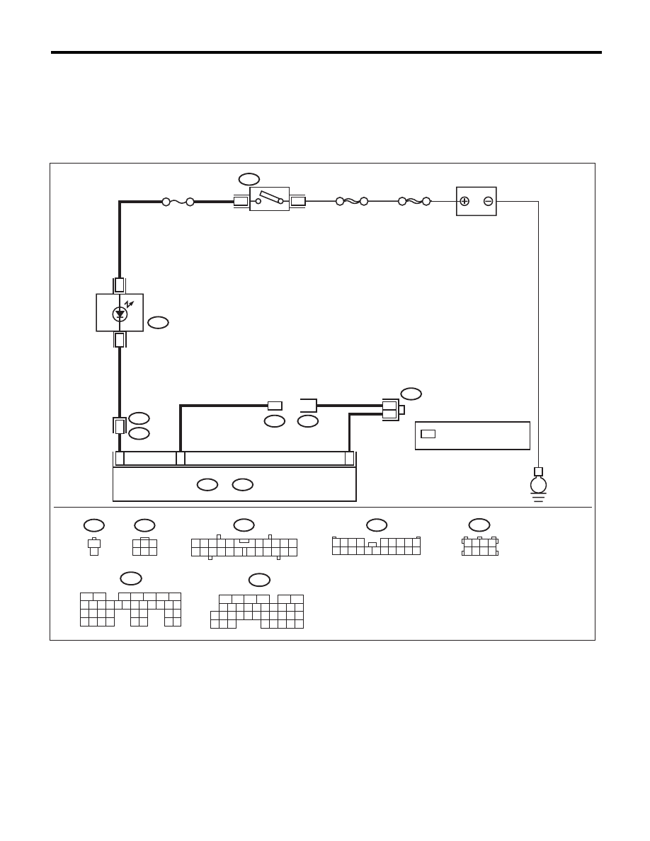
Malfunction Indicator Light
ENGINE (DIAGNOSTICS)
E: MALFUNCTION INDICATOR LIGHT DOES NOT BLINK
DIAGNOSIS:
• The malfunction indicator light circuit is open or shorted.
• The delivery (test) mode connector circuit is open.
TROUBLE SYMPTOM:
Malfunction indicator light does not blink during Inspection Mode.
WIRING DIAGRAM:
EN-05698
i10
16
3
B135
B:
8
i3
B38
B75
B76
1
1
B136
C:
E
3
B72
SBF-6
1
MAIN SBF
No.5
B135
B136
B:
C:
B72
B75
2
1
3
4
6
2
i10
B38
1 2 3 4
5 6 7 8 9
10 11 12 13
15 16 17
19 20
2
1
3 4
6 7 8 9 10
22
21
20
19
18
17
16
15
14
13
12
11
5
1 2 3 4
5 6
8
B122
14
18
7
1
5
C11
C6
B122
B27
*
*
*
16
10 11 12 13 14 15
25
24
30
9
8
7
17 18 19 20
28
21 22 23
29
32
31
1
2
3
4
5
6
27
26
33 34 35
5
6
7
8
2
1
9
4
3
10
24
22 23
25
11 12 13 14 15
26 27
28
16 17 18 19
20 21
29 30 31
32 33
34 35
IGNITION
SWITCH
BATTERY
COMBINATION
METER
ECM
: TERMINAL No. OPTIONAL
ARRANGEMENT
DELIVERY (TEST)
MODE CONNECTOR

EN(H4SO)(diag)-61
Malfunction Indicator Light
ENGINE (DIAGNOSTICS)
Step
Check
Yes
No
1
CHECK STATUS OF MALFUNCTION INDI-
CATOR LIGHT.
1) Turn the ignition switch to OFF.
2) Disconnect the delivery (test) mode connec-
tor.
3) Turn the ignition switch to ON. (engine OFF)
Does the malfunction indicator
light illuminate?
Go to step 2.
Repair the mal-
function indicator
light circuit. <Ref.
to
EN(H4SO)(diag)-
57, MALFUNC-
TION INDICATOR
LIGHT DOES NOT
COME ON, Mal-
function Indicator
Light.>
2
CHECK HARNESS BETWEEN ECM AND
COMBINATION METER CONNECTOR.
1) Turn the ignition switch to OFF.
2) Disconnect the connectors from ECM.
3) Turn the ignition switch to ON.
Does the malfunction indicator
light illuminate?
Repair the short
circuit of harness
between ECM and
combination meter
connector.
Go to step 3.
3
CHECK HARNESS BETWEEN ECM AND DE-
LIVERY (TEST) MODE CONNECTOR.
1) Turn the ignition switch to OFF.
2) Disconnect the connectors from ECM.
3) Measure the resistance of harness between
ECM and delivery (test) mode connector.
Connector & terminal
(B76) No. 1 — (B136) No. 6:
(B75) No. 1 — (B135) No. 27:
Is the resistance less than 1
:? Go to step 4.
Repair the harness
and connector.
NOTE:
In this case, repair
the following item:
• Open circuit of
harness between
ECM and delivery
(test) mode con-
nector
• Poor contact in
joint connector
4
CHECK POOR CONTACT.
Check for poor contact of the ECM connector.
Is there poor contact in ECM
connector?
Repair the poor
contact of ECM
connector.
Replace the ECM.
<Ref. to
FU(H4SO)-39,
Engine Control
Module (ECM).>
EN(H4SO)(diag)-62
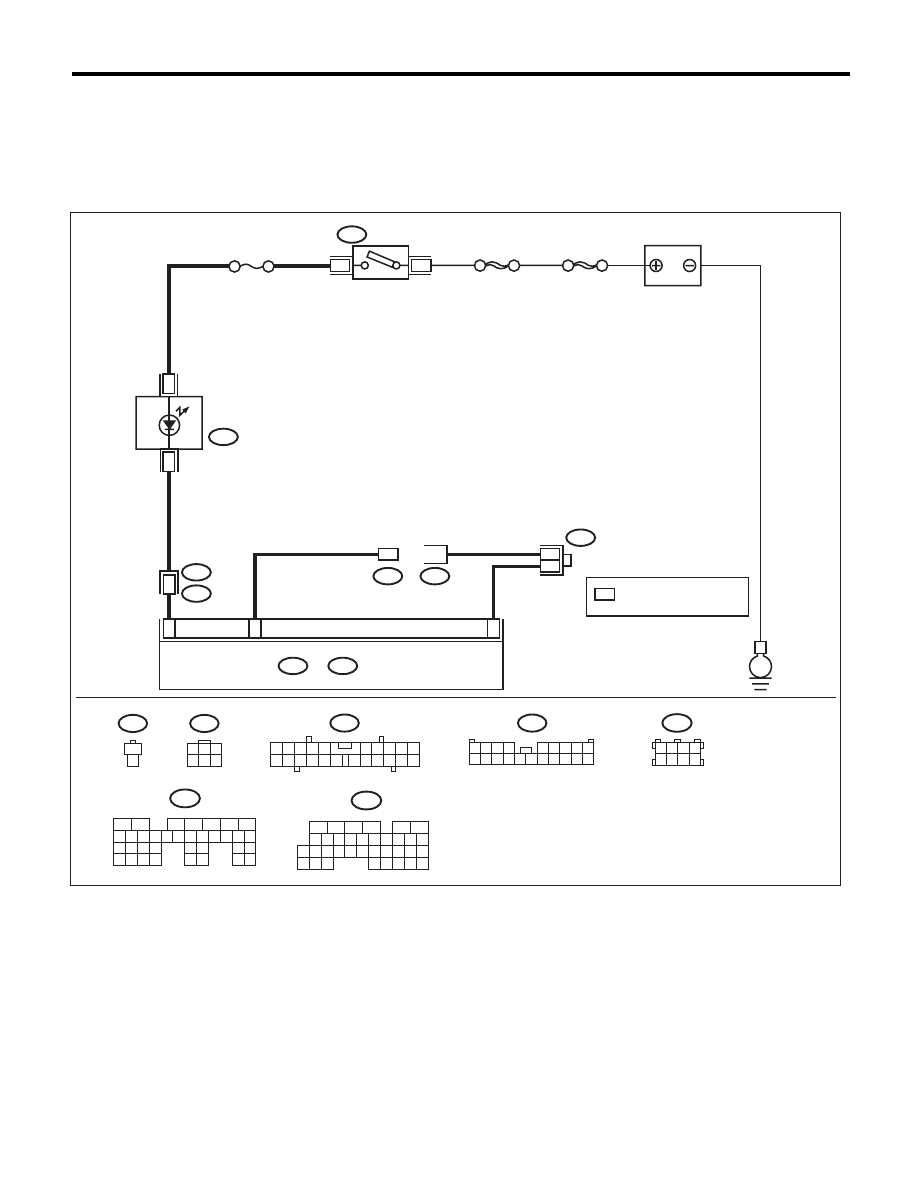
Malfunction Indicator Light
ENGINE (DIAGNOSTICS)
F: MALFUNCTION INDICATOR LIGHT REMAINS BLINKING
DIAGNOSIS:
The delivery (test) mode connector circuit is shorted.
TROUBLE SYMPTOM:
Malfunction indicator light blinks when delivery (test) mode connector is not connected.
WIRING DIAGRAM:
EN-05698
i10
16
3
B135
B:
8
i3
B38
B75
B76
1
1
B136
C:
E
3
B72
SBF-6
1
MAIN SBF
No.5
B135
B136
B:
C:
B72
B75
2
1
3
4
6
2
i10
B38
1 2 3 4
5 6 7 8 9
10 11 12 13
15 16 17
19 20
2
1
3 4
6 7 8 9 10
22
21
20
19
18
17
16
15
14
13
12
11
5
1 2 3 4
5 6
8
B122
14
18
7
1
5
C11
C6
B122
B27
*
*
*
16
10 11 12 13 14 15
25
24
30
9
8
7
17 18 19 20
28
21 22 23
29
32
31
1
2
3
4
5
6
27
26
33 34 35
5
6
7
8
2
1
9
4
3
10
24
22 23
25
11 12 13 14 15
26 27
28
16 17 18 19
20 21
29 30 31
32 33
34 35
IGNITION
SWITCH
BATTERY
COMBINATION
METER
ECM
: TERMINAL No. OPTIONAL
ARRANGEMENT
DELIVERY (TEST)
MODE CONNECTOR
Нет комментариевНе стесняйтесь поделиться с нами вашим ценным мнением.
Текст