Subaru Legacy IV (2008 year). Service manual — part 113
EN(H4SO)(diag)-55
Malfunction Indicator Light
ENGINE (DIAGNOSTICS)
16.Malfunction Indicator Light
A: PROCEDURE
1. Activation of malfunction indicator light. <Ref. to EN(H4SO)(diag)-56, ACTIVATION OF MALFUNCTION INDICATOR LIGHT,
Malfunction Indicator Light.>
p
2. Malfunction indicator light does not come on. <Ref. to EN(H4SO)(diag)-57, MALFUNCTION INDICATOR LIGHT DOES NOT
COME ON, Malfunction Indicator Light.>
p
3. Malfunction indicator light does not go off. <Ref. to EN(H4SO)(diag)-59, MALFUNCTION INDICATOR LIGHT DOES NOT GO
OFF, Malfunction Indicator Light.>
p
4. Malfunction indicator light does not blink. <Ref. to EN(H4SO)(diag)-60, MALFUNCTION INDICATOR LIGHT DOES NOT
BLINK, Malfunction Indicator Light.>
p
5. Malfunction indicator light remains blinking. <Ref. to EN(H4SO)(diag)-62, MALFUNCTION INDICATOR LIGHT REMAINS
BLINKING, Malfunction Indicator Light.>
EN(H4SO)(diag)-56
Malfunction Indicator Light
ENGINE (DIAGNOSTICS)
B: ACTIVATION OF MALFUNCTION
INDICATOR LIGHT
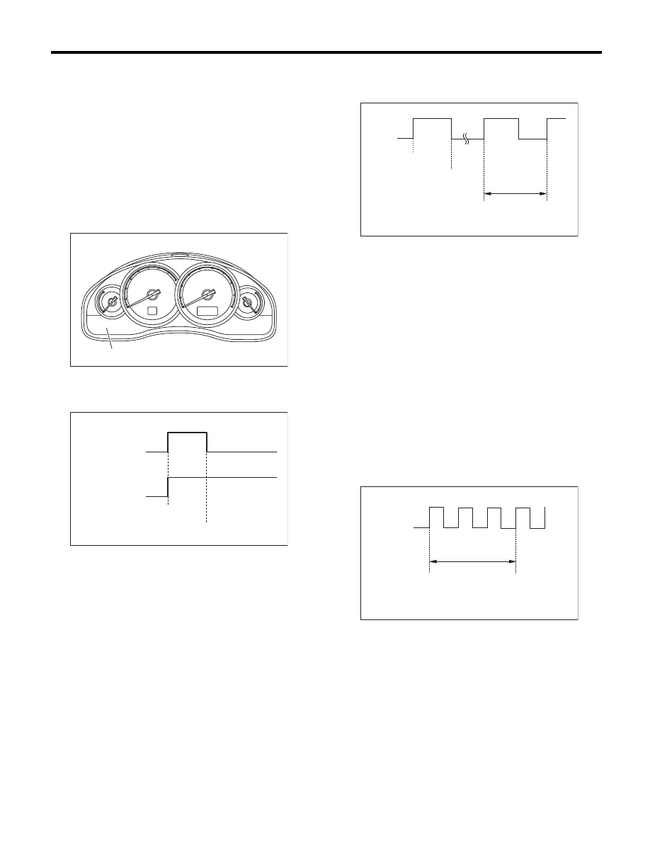
1) When the ignition switch is turned to ON (engine
OFF), the malfunction indicator light (A) in the com-
bination meter illuminates.
NOTE:
If the malfunction indicator light does not illuminate,
perform diagnostics of the malfunction indicator
light circuit or the combination meter circuit. <Ref.
to EN(H4SO)(diag)-57, MALFUNCTION INDICA-
TOR LIGHT DOES NOT COME ON, Malfunction
Indicator Light.>
2) After starting the engine, the malfunction indica-
tor light goes out. If it does not go off, either the en-
gine or emission control system has malfunction.
3) If the diagnostic system detects a misfire which
could damage the catalyst, the malfunction indica-
tor light will blink at a cycle of 1 Hz.
4) Turn the ignition switch to OFF and connect the
delivery (test) mode connector.
(1) When the ignition switch is turned to ON
(engine OFF), the malfunction indicator light il-
luminates.
(2) After the engine starts, malfunction indicator
light blinks in a cycle of 0.5 Hz. (During diagno-
sis)
(3) Malfunction indicator light blinks at a cycle of
3 Hz after diagnosis if there is no trouble. Mal-
function indicator light illuminates if faulty.
(1) No faulty
(2) Trouble occurs
(3) ON
(4) OFF
(5) Ignition switch ON
(6) Engine start
CHECK
ENGINE
(A)
EN-05736
EN-01679
(1)
(2)
(5)
(6)
(3)
(4)
(3)
(4)
(1) ON
(2) OFF
(3) Ignition switch ON
(4) Engine start
(5) Misfire start
(6) 1 second
(1) ON
(2) OFF
(3) Ignition switch ON
(4) 1 second
EN-01680
(2)
(1)
(3)
(4)
(5)
(6)
EN-01681
(2)
(1)
(4)
(3)
EN(H4SO)(diag)-57
Malfunction Indicator Light
ENGINE (DIAGNOSTICS)
C: MALFUNCTION INDICATOR LIGHT DOES NOT COME ON
DIAGNOSIS:
The malfunction indicator light circuit is open or shorted.
TROUBLE SYMPTOM:
When the ignition switch is turned to ON (engine OFF), malfunction indicator light does not illuminate.
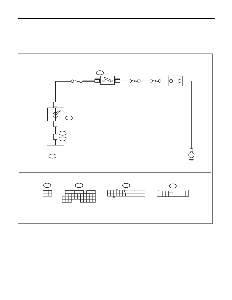
WIRING DIAGRAM:
EN-05697
3
B72
i3
B38
B136
i10
SBF-6
1
11
3
B72
8
MAIN SBF
No.5
16
E
1
3
4 5 6
2
B136
i10
B38
1 2 3 4
5 6 7 8 9
10 11 12 13 14 15 16 17 18 19 20
2
1
3 4
6 7 8 9 10
22
21
20
19
18
17
16
15
14
13
12
11
5
16
10 11 12 13 14 15
25
24
30
9
8
7
17 18 19 20
28
21 22 23
29
32
31
1
2
3
4
5
6
27
26
33 34 35
ECM
COMBINATION
METER
IGNITION
SWITCH
BATTERY
EN(H4SO)(diag)-58
Malfunction Indicator Light
ENGINE (DIAGNOSTICS)
Step
Check
Yes
No
1
CHECK OUTPUT SIGNAL OF ECM.
1) Turn the ignition switch to ON.
2) Measure the voltage between ECM connec-
tor and chassis ground.
Connector & terminal
(B136) No. 11 (+) — Chassis ground (–):
Is the voltage 10 V or more?
Go to step 5.
Go to step 2.
2
CHECK HARNESS BETWEEN ECM AND
COMBINATION METER CONNECTOR.
1) Turn the ignition switch to OFF.
2) Remove the combination meter. <Ref. to
IDI-22, Combination Meter.>
3) Disconnect the connector from ECM and
combination meter.
4) Measure the resistance of harness between
ECM and combination meter connector.
Connector & terminal
(B136) No. 11 — (i10) No. 16:
Is the resistance less than 1
:? Go to step 3.
Repair the harness
and connector.
NOTE:
In this case, repair
the following item:
• Open circuit of
harness between
ECM and combi-
nation meter con-
nector
• Poor contact of
coupling connector
3
CHECK POOR CONTACT.
Check for poor contact of combination meter
connector.
Is there poor contact in combi-
nation meter connector?
Repair the poor
contact of combi-
nation meter con-
nector.
Go to step 4.
4
CHECK HARNESS BETWEEN COMBINA-
TION METER AND IGNITION SWITCH CON-
NECTOR.
1) Turn the ignition switch to ON.
2) Measure the voltage between combination
meter connector and chassis ground.
Connector & terminal
(i10) No. 3 (+) — Chassis ground (–):
Is the voltage 10 V or more?
Replace the com-
bination meter
board. <Ref. to IDI-
22, Combination
Meter.>
Check the follow-
ing item and repair
if necessary.
NOTE:
• Blown out of fuse
(No. 5)
• Open or short
circuit in harness
between fuse (No.
5) and battery ter-
minal
• Poor contact in
ignition switch con-
nector
5
CHECK POOR CONTACT.
Check for poor connection by shaking or pulling
ECM harness.
Does the malfunction indicator
light illuminate?
Repair the poor
contact of ECM
connector.
Go to step 6.
6
CHECK ECM CONNECTOR.
Check the connection of ECM connector.
Is the ECM connector correctly
connected?
Replace the ECM.
<Ref. to
FU(H4SO)-39,
Engine Control
Module (ECM).>
Repair the connec-
tion of ECM con-
nector.
Нет комментариевНе стесняйтесь поделиться с нами вашим ценным мнением.
Текст