Subaru Legacy IV (2008 year). Service manual — part 940

VDC(diag)-75
Diagnostic Procedure with Diagnostic Trouble Code (DTC)
VEHICLE DYNAMICS CONTROL (VDC) (DIAGNOSTICS)
AK:DTC C0057 ECM COMMUNICATION CIRCUIT
DTC DETECTING CONDITION:
No CAN signal from ECM.
TROUBLE SYMPTOM:
• ABS does not operate.
• VDC does not operate.
Step
Check
Yes
No
1
CHECK LAN SYSTEM.
Perform the diagnosis for LAN system. <Ref. to
LAN(diag)-27, OPERATION, Read Diagnostic
Trouble Code (DTC).>
Is there any fault in LAN sys-
tem?
Perform the diag-
nosis according to
DTC for LAN sys-
tem.
Go to step 2.
2
CHECK POOR CONTACT IN CONNECTORS. Is there poor contact in ECM
connector?
Repair the connec-
tor.
Go to step 3.
3
CHECK ECM.
Is ECM normal?
Go to step 4.
Replace the ECM.
4
CHECK VDCCM&H/U.
1) Connect all connectors.
2) Clear the memory. <Ref. to VDC(diag)-23,
Clear Memory Mode.>
3) Perform the Inspection Mode. <Ref. to
VDC(diag)-22, Inspection Mode.>
4) Read the DTC.
Is the same DTC displayed?
Replace the
VDCCM only.
<Ref. to VDC-10,
REPLACEMENT,
VDC Control Mod-
ule and Hydraulic
Control Unit
(VDCCM&H/U).>
Go to step 5.
5
CHECK OTHER DTC DETECTION.
Is any other DTC displayed?
Perform the diag-
nosis according to
DTC. <Ref. to
VDC(diag)-34, List
of Diagnostic Trou-
ble Code (DTC).>
It results from a
temporary noise
interference.

VDC(diag)-76
Diagnostic Procedure with Diagnostic Trouble Code (DTC)
VEHICLE DYNAMICS CONTROL (VDC) (DIAGNOSTICS)
AL:DTC C0057 ECM CONTROL SYSTEM
DTC DETECTING CONDITION:
Cooperation control prohibition of ECM
TROUBLE SYMPTOM:
• ABS does not operate.
• VDC does not operate.
NOTE:
Warning lights go off if the cooperation control of ECM returns.
Step
Check
Yes
No
1
CHECK WARNING LIGHT.
Check whether the VDC warning light illumi-
nates after driving for 1 minute or more at a
speed of 10 km/h or more.
Does the VDC warning light illu-
minate?
Go to step 2.
VDC is normal.
Perform the Clear
Memory Mode.
NOTE:
If cranking opera-
tion is performed
while driving, DTC
may be memo-
rized.
2
CHECK POOR CONTACT IN CONNECTORS. Is there poor contact in ECM
connector?
Repair the connec-
tor.
Go to step 3.
3
CHECK ECM.
Is ECM normal?
Go to step 4.
Replace the ECM.
4
CHECK VDCCM&H/U.
1) Connect all connectors.
2) Clear the memory. <Ref. to VDC(diag)-23,
Clear Memory Mode.>
3) Perform the Inspection Mode. <Ref. to
VDC(diag)-22, Inspection Mode.>
4) Read the DTC.
Is the same DTC displayed?
Replace the
VDCCM only.
<Ref. to VDC-10,
REPLACEMENT,
VDC Control Mod-
ule and Hydraulic
Control Unit
(VDCCM&H/U).>
Go to step 5.
5
CHECK OTHER DTC DETECTION.
Is any other DTC displayed?
Perform the diag-
nosis according to
DTC. <Ref. to
VDC(diag)-34, List
of Diagnostic Trou-
ble Code (DTC).>
It results from a
temporary noise
interference.
VDC(diag)-77
Diagnostic Procedure with Diagnostic Trouble Code (DTC)
VEHICLE DYNAMICS CONTROL (VDC) (DIAGNOSTICS)
AM:DTC C0071 STEERING ANGLE SENSOR OFFSET IS TOO BIG
DTC DETECTING CONDITION:
Defective steering angle sensor
TROUBLE SYMPTOM:
VDC does not operate.
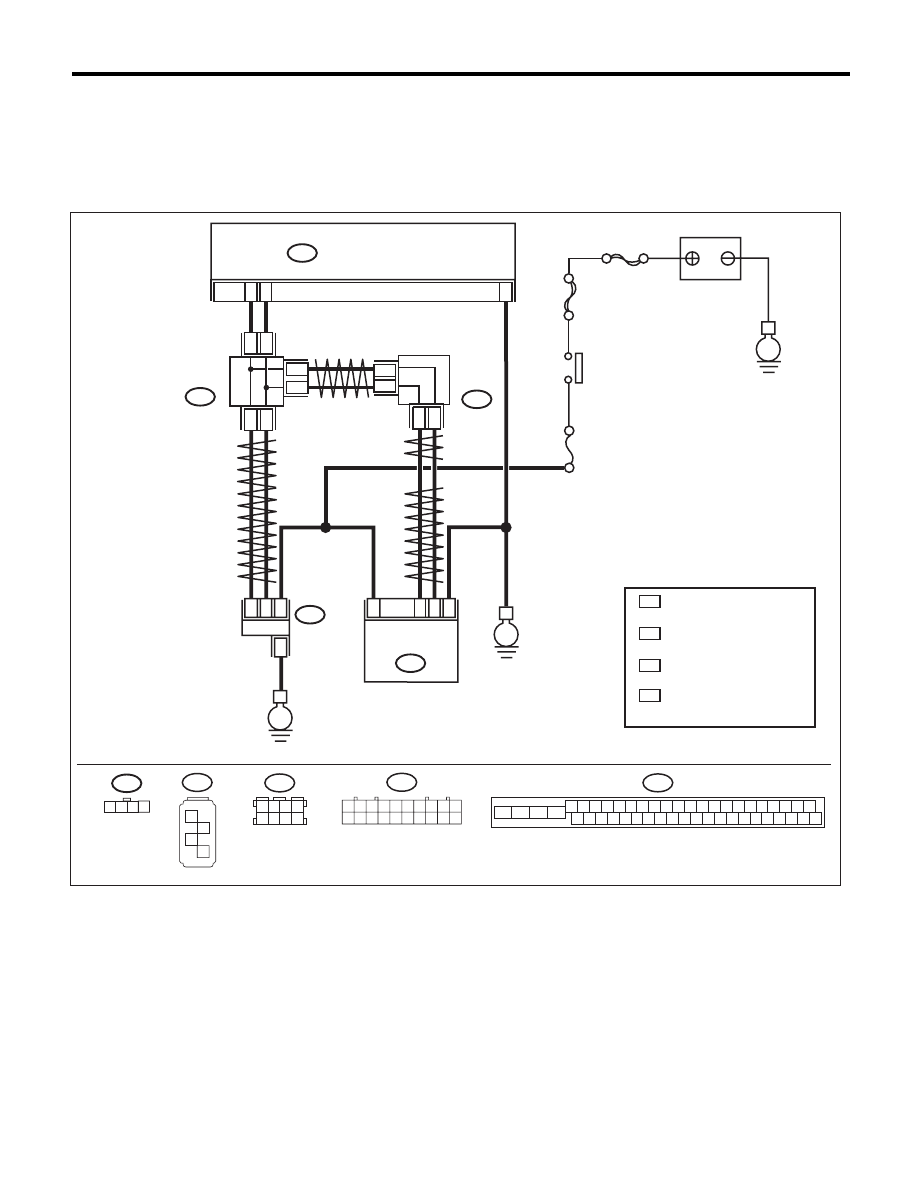
WIRING DIAGRAM:
VDC00473
1 2 3 4
B310
VDCCM & H/U
25
10
35
B231
B230
2
4
1
1
4
2
3
3
STEERING
ANGLE
SENSOR
YAW RATE &
LATERAL G
SENSOR
E
E
B231
SBF-6
MAIN SBF
No.33
E
IGNITION
SWITCH
BATTERY
B310
4 5 6 7 8 9
26 27 28 29 30
2 3
1
31 32 33 34 35 36
10 11
14 15 16 17 18 19
37 38 39 40
12 13
41 42 43 44 45 46
20 21
23
24
22
25
B230
1
2
3
4
TWISTED PAIR LINE
TWISTED PAIR LINE
B365
B170
CAN
JOINT
CONNECTOR
4
*
3
*
4
3
*
*
2
1 :
:
*
*
CAN
JOINT
CONNECTOR
TERMINAL No. OPTIONAL
ARRANGEMENT AMONG
1, 2, 3,11,12 AND 13
TERMINAL No. OPTIONAL
ARRANGEMENT AMONG
8, 9, 10, 18, 19 AND 20
4
3 :
:
*
*
TERMINAL No. OPTIONAL
ARRANGEMENT AMONG
1, 2, 5 AND 6
TERMINAL No. OPTIONAL
ARRANGEMENT AMONG
3, 4, 7 AND 8
2
1
* *
2
1
* *
2
1
*
*
TWISTED
PAIR LINE
B170
3 4
5 6
1 2
7 8
1 2 3 4 5 6 7 8 9 10
11 12 13 14 15 16 17 18 19 20
B365

VDC(diag)-78
Diagnostic Procedure with Diagnostic Trouble Code (DTC)
VEHICLE DYNAMICS CONTROL (VDC) (DIAGNOSTICS)
Step
Check
Yes
No
1
CHECK STEERING WHEEL.
1) Drive the vehicle on a flat road.
2) Park the vehicle straight.
3) Check the steering wheel for deviation from
center.
Is the deviation from the center
of steering wheel less than 5°?
Go to step 2.
Perform the cen-
tering adjustment
of steering wheel.
2
CHECK VDCCM&H/U.
1) Turn the ignition switch to OFF.
2) Connect all connectors.
3) Clear the memory. <Ref. to VDC(diag)-23,
Clear Memory Mode.>
4) Perform the Inspection Mode. <Ref. to
VDC(diag)-22, Inspection Mode.>
5) Read the DTC.
Is the same DTC displayed?
Replace the
VDCCM only.
<Ref. to VDC-10,
REPLACEMENT,
VDC Control Mod-
ule and Hydraulic
Control Unit
(VDCCM&H/U).>
Go to step 3.
3
CHECK OTHER DTC DETECTION.
Is any other DTC displayed?
Perform the diag-
nosis according to
DTC. <Ref. to
VDC(diag)-34, List
of Diagnostic Trou-
ble Code (DTC).>
Temporary poor
contact occurs.
Нет комментариевНе стесняйтесь поделиться с нами вашим ценным мнением.
Текст