Subaru Legacy IV (2008 year). Service manual — part 941
VDC(diag)-79
Diagnostic Procedure with Diagnostic Trouble Code (DTC)
VEHICLE DYNAMICS CONTROL (VDC) (DIAGNOSTICS)
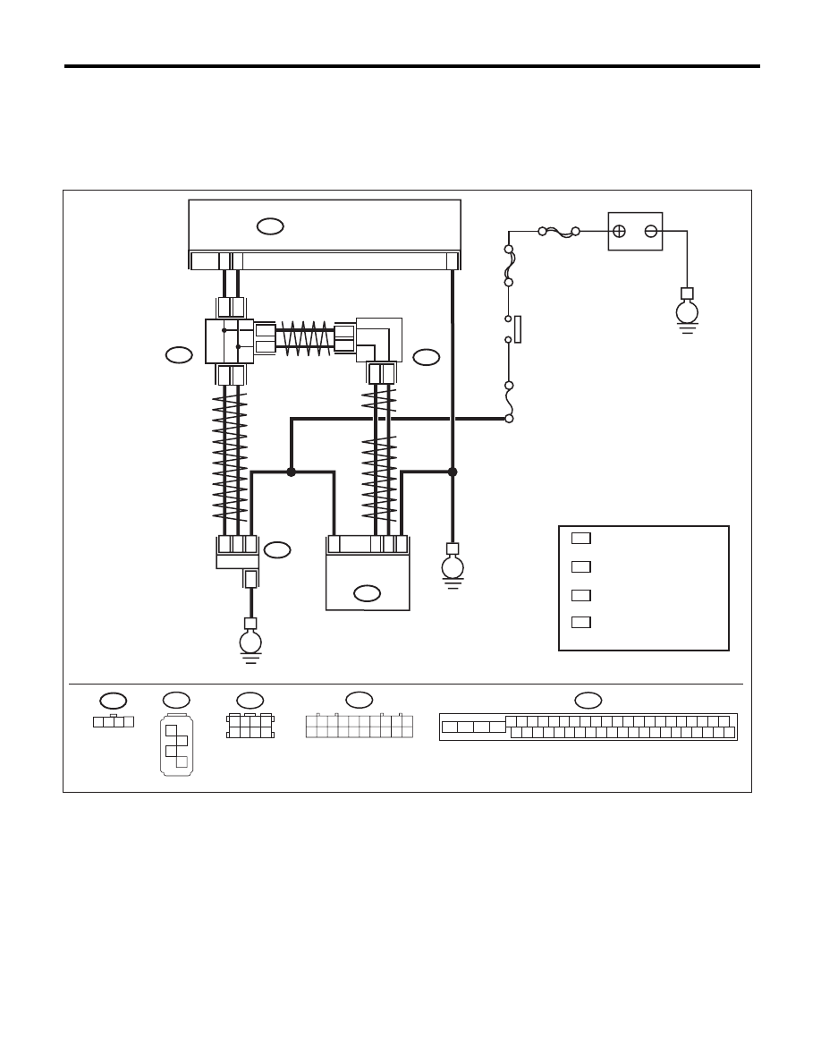
AN:DTC C0071 CHANGE RANGE OF STEERING ANGLE SENSOR IS TOO BIG
DTC DETECTING CONDITION:
Defective steering angle sensor
TROUBLE SYMPTOM:
VDC does not operate.
WIRING DIAGRAM:
VDC00473
1 2 3 4
B310
VDCCM & H/U
25
10
35
B231
B230
2
4
1
1
4
2
3
3
STEERING
ANGLE
SENSOR
YAW RATE &
LATERAL G
SENSOR
E
E
B231
SBF-6
MAIN SBF
No.33
E
IGNITION
SWITCH
BATTERY
B310
4 5 6 7 8 9
26 27 28 29 30
2 3
1
31 32 33 34 35 36
10 11
14 15 16 17 18 19
37 38 39 40
12 13
41 42 43 44 45 46
20 21
23
24
22
25
B230
1
2
3
4
TWISTED PAIR LINE
TWISTED PAIR LINE
B365
B170
CAN
JOINT
CONNECTOR
4
*
3
*
4
3
*
*
2
1 :
:
*
*
CAN
JOINT
CONNECTOR
TERMINAL No. OPTIONAL
ARRANGEMENT AMONG
1, 2, 3,11,12 AND 13
TERMINAL No. OPTIONAL
ARRANGEMENT AMONG
8, 9, 10, 18, 19 AND 20
4
3 :
:
*
*
TERMINAL No. OPTIONAL
ARRANGEMENT AMONG
1, 2, 5 AND 6
TERMINAL No. OPTIONAL
ARRANGEMENT AMONG
3, 4, 7 AND 8
2
1
* *
2
1
* *
2
1
*
*
TWISTED
PAIR LINE
B170
3 4
5 6
1 2
7 8
1 2 3 4 5 6 7 8 9 10
11 12 13 14 15 16 17 18 19 20
B365

VDC(diag)-80
Diagnostic Procedure with Diagnostic Trouble Code (DTC)
VEHICLE DYNAMICS CONTROL (VDC) (DIAGNOSTICS)
Step
Check
Yes
No
1
CHECK VDCCM&H/U.
1) Turn the ignition switch to OFF.
2) Connect all connectors.
3) Clear the memory. <Ref. to VDC(diag)-23,
Clear Memory Mode.>
4) Perform the Inspection Mode. <Ref. to
VDC(diag)-22, Inspection Mode.>
5) Read the DTC.
Is the same DTC displayed?
Replace the
VDCCM only.
<Ref. to VDC-10,
REPLACEMENT,
VDC Control Mod-
ule and Hydraulic
Control Unit
(VDCCM&H/U).>
Go to step 2.
2
CHECK OTHER DTC DETECTION.
Is any other DTC displayed?
Perform the diag-
nosis according to
DTC. <Ref. to
VDC(diag)-34, List
of Diagnostic Trou-
ble Code (DTC).>
Temporary poor
contact occurs.
VDC(diag)-81
Diagnostic Procedure with Diagnostic Trouble Code (DTC)
VEHICLE DYNAMICS CONTROL (VDC) (DIAGNOSTICS)
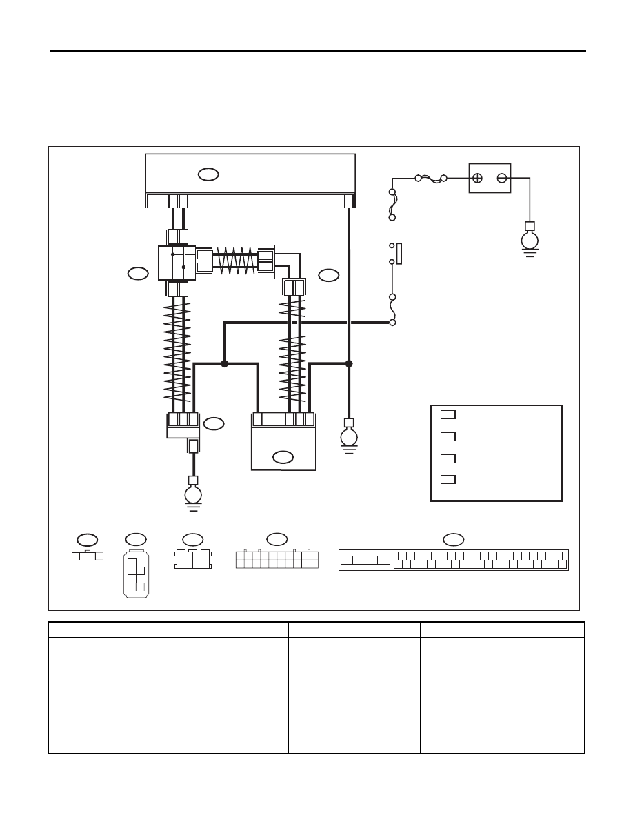
AO:DTC C0071 STEER ANGLE SENSOR OP
DTC DETECTING CONDITION:
Signal does not come from steering angle sensor.
TROUBLE SYMPTOM:
VDC does not operate.
WIRING DIAGRAM:
Step
Check
Yes
No
1
CHECK POWER SUPPLY FOR STEERING
ANGLE SENSOR.
1) Turn the ignition switch to OFF.
2) Disconnect the connector from steering
angle sensor.
3) Turn the ignition switch to ON.
4) Measure the voltage between the steering
angle sensor and chassis ground.
Connector & terminal
(B231) No. 4 (+) — Chassis ground (–):
Is the voltage 10 — 15 V?
Go to step 2.
Repair the power
supply circuit of
steering angle sen-
sor.
VDC00473
1 2 3 4
B310
VDCCM & H/U
25
10
35
B231
B230
2
4
1
1
4
2
3
3
STEERING
ANGLE
SENSOR
YAW RATE &
LATERAL G
SENSOR
E
E
B231
SBF-6
MAIN SBF
No.33
E
IGNITION
SWITCH
BATTERY
B310
4 5 6 7 8 9
26 27 28 29 30
2 3
1
31 32 33 34 35 36
10 11
14 15 16 17 18 19
37 38 39 40
12 13
41 42 43 44 45 46
20 21
23
24
22
25
B230
1
2
3
4
TWISTED PAIR LINE
TWISTED PAIR LINE
B365
B170
CAN
JOINT
CONNECTOR
4
*
3
*
4
3
*
*
2
1 :
:
*
*
CAN
JOINT
CONNECTOR
TERMINAL No. OPTIONAL
ARRANGEMENT AMONG
1, 2, 3,11,12 AND 13
TERMINAL No. OPTIONAL
ARRANGEMENT AMONG
8, 9, 10, 18, 19 AND 20
4
3 :
:
*
*
TERMINAL No. OPTIONAL
ARRANGEMENT AMONG
1, 2, 5 AND 6
TERMINAL No. OPTIONAL
ARRANGEMENT AMONG
3, 4, 7 AND 8
2
1
* *
2
1
* *
2
1
*
*
TWISTED
PAIR LINE
B170
3 4
5 6
1 2
7 8
1 2 3 4 5 6 7 8 9 10
11 12 13 14 15 16 17 18 19 20
B365

VDC(diag)-82
Diagnostic Procedure with Diagnostic Trouble Code (DTC)
VEHICLE DYNAMICS CONTROL (VDC) (DIAGNOSTICS)
2
CHECK GROUND CIRCUIT OF STEERING
ANGLE SENSOR.
Measure the resistance between steering angle
sensor and chassis ground.
Connector & terminal
(B231) No. 3 — Chassis ground:
Is the resistance less than 0.5
:? Go to step 3.
Repair ground cir-
cuit in the steering
angle sensor.
3
CHECK STEERING ANGLE SENSOR HAR-
NESS.
1) Disconnect the connector from the
VDCCM&H/U.
2) Measure the resistance between
VDCCM&H/U and steering angel sensor.
Connector & terminal
(B231) No. 1 — (B310) No. 10:
(B231) No. 2 — (B310) No. 35:
Is the resistance less than 0.5
:? Go to step 4.
Repair the harness
between the steer-
ing angle sensor
and VDCCM&H/U.
4
CHECK GROUND SHORT CIRCUIT OF
STEERING ANGLE SENSOR HARNESS.
Measure the resistance between steering angle
sensor and chassis ground.
Connector & terminal
(B231) No. 1 — Chassis ground:
(B231) No. 2 — Chassis ground:
Is the resistance 1 M
: or
more?
Go to step 5.
Repair the harness
between the steer-
ing angle sensor
and VDCCM&H/U.
5
CHECK STEERING ANGLE SENSOR.
1) Turn the ignition switch to OFF.
2) Connect all connectors.
3) Clear the memory. <Ref. to VDC(diag)-23,
Clear Memory Mode.>
4) Perform the Inspection Mode. <Ref. to
VDC(diag)-22, Inspection Mode.>
5) Read the DTC.
Is the same DTC displayed?
Go to step 6.
Go to step 7.
6
CHECK VDCCM&H/U.
1) Turn the ignition switch to OFF.
2) Replace the steering angle sensor.
3) Clear the memory. <Ref. to VDC(diag)-23,
Clear Memory Mode.>
4) Perform the Inspection Mode. <Ref. to
VDC(diag)-22, Inspection Mode.>
5) Read the DTC.
Is the same DTC displayed?
Replace the
VDCCM only.
<Ref. to VDC-10,
REPLACEMENT,
VDC Control Mod-
ule and Hydraulic
Control Unit
(VDCCM&H/U).>
Go to step 8.
7
CHECK OTHER DTC DETECTION.
Is any other DTC displayed?
Perform the diag-
nosis according to
DTC. <Ref. to
VDC(diag)-34, List
of Diagnostic Trou-
ble Code (DTC).>
Temporary poor
contact occurs.
8
CHECK OTHER DTC DETECTION.
Is any other DTC displayed?
Perform the diag-
nosis according to
DTC. <Ref. to
VDC(diag)-34, List
of Diagnostic Trou-
ble Code (DTC).>
Original steering
angle sensor mal-
function
Step
Check
Yes
No
Нет комментариевНе стесняйтесь поделиться с нами вашим ценным мнением.
Текст