Subaru Legacy IV (2008 year). Service manual — part 698
4AT(diag)-13
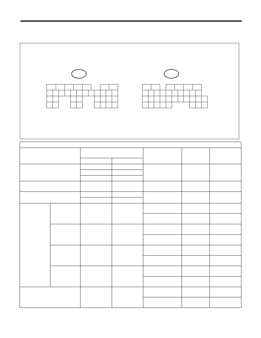
Transmission Control Module (TCM) I/O Signal
AUTOMATIC TRANSMISSION (DIAGNOSTICS)
5. Transmission Control Module (TCM) I/O Signal
A: ELECTRICAL SPECIFICATION
Check with ignition switch ON.
Contents
Measured terminal
(Connector & Terminal No.)
Measuring condition
Voltage (V)
Resistance (
:)
Positive terminal
Ground terminal
Backup power supply
(B55) No. 27
Chassis ground
—
10 — 13
—
(B55) No. 26
Chassis ground
(B55) No. 25
Chassis ground
ACC power supply
(B55) No. 12
Chassis ground
Ignition
Switch ACC
10 — 13
—
Ignition power supply
(B55) No. 1
Chassis ground
Ignition
Switch ON
10 — 13
—
(B55) No. 2
Chassis ground
Inhibitor switch
“P” range
switch
(B54) No. 14
Chassis ground
Select lever
“P” range
Less than 1
—
Select lever
Except “P” range
8 or more
—
“N” range
switch
(B54) No. 11
Chassis ground
Select lever
“N” range
Less than 1
—
Select lever
Except “N” range
8 or more
—
“R” range
switch
(B54) No. 13
Chassis ground
Select lever
“R” range
Less than 1
—
Select lever
Except “R” range
8 or more
—
“D” range
switch
(B54) No. 10
Chassis ground
Select lever
“D” range
Less than 1
—
Select lever
Except “D” range
8 or more
—
ATF temperature sensor
(B54) No. 23
(B54) No. 12
ATF temperature
20°C (68°F)
3.5 — 4.3
2.5k — 7.0 k
ATF temperature
80°C (176°F)
1.0 — 2.2
300 — 800
5
6
7
8
2
1
9
4
3
10
24
22
23
25
11
12
13
14
15
26
27
28
16
17
18
19
20
21
29
30
31
32
33
34
35
B55
TO
TO
5
6
7
8
2
1
9
4
3
10
24
22
23
25
11
12
13
14
15
26
27
28
16
17
18
19
20
21
33
34
29
32
30
31
35
B54
AT-03733

4AT(diag)-14
Transmission Control Module (TCM) I/O Signal
AUTOMATIC TRANSMISSION (DIAGNOSTICS)
ATF temperature sensor ground
(B54) No. 12
Chassis ground
—
0
Less than 1
(When inserting
connector)
f (When dis-
connecting con-
nector)
Rear vehicle speed sensor
(B54) No. 26
(B54) No. 15
20 km/h (12 MPH)
Vehicle speed at
least
2 or more
(AC range)
—
Rear vehicle speed sensor
ground
(B54) No. 15
Chassis ground
—
0
Less than 1
(When inserting
connector)
f (When dis-
connecting con-
nector)
Front vehicle speed sensor
(B54) No. 27
(B54) No. 16
—
—
450 — 650
Front vehicle speed sensor
ground
(B54) No. 16
Chassis ground
—
—
—
Torque converter turbine speed
sensor
(B54) No. 1
(B54) No. 2
Engine idling after
warm up (“D” range)
0
450 — 650
Engine idling after
warm up (“N” range)
1 or more
(AC range)
Torque converter turbine speed
sensor ground
(B54) No. 2
Chassis ground
—
—
—
Engine speed signal
(B55) No. 11
Chassis ground
Ignition switch ON
(engine OFF)
Less than 1
—
Engine start
5 or more
(AC range)
—
Line pressure linear solenoid
(B54) No. 4
(B54) No. 3
Ignition switch ON
(with engine OFF)
Throttle fully closed
in “R” range after
warm up.
3.7 — 7.7
4.0 — 6.0
Ignition switch ON
(with engine OFF)
Throttle fully closed
in “R” range after
warm up.
1.1 — 5.1
Line pressure linear solenoid
ground
(B54) No. 3
Chassis ground
—
Less than 1
Less than 1
Lock-up duty solenoid
(B54) No. 6
Chassis ground
When lock up
occurs.
10.5 or more
2.0 — 4.5
When lock up is
released.
Less than 1
Transfer duty solenoid
(B54) No. 5
Chassis ground
With fuse installed to
FWD switch
Less than 1
2.0 — 4.5
With fuse removed
from FWD switch
(1st gear)
2.0 — 3.0
2-4 brake duty solenoid
(B55) No. 4
Chassis ground
“P” or “N” range
5.0 or more
2.0 — 4.5
2nd or 4th gear
Less than 1
High clutch duty solenoid
(B55) No. 6
Chassis ground
3rd or 4th gear
Less than 1
2.0 — 4.5
“P” or “N” range
5.0 or more
Check with ignition switch ON.
Contents
Measured terminal
(Connector & Terminal No.)
Measuring condition
Voltage (V)
Resistance (
:)
Positive terminal
Ground terminal
4AT(diag)-15
Transmission Control Module (TCM) I/O Signal
AUTOMATIC TRANSMISSION (DIAGNOSTICS)
Low clutch duty solenoid
(B55) No. 7
Chassis ground
1st or 2nd gear
Less than 1
2.0 — 4.5
“P” or “N” range
5.0 or more
Low & reverse duty solenoid
(B55) No. 5
Chassis ground
Except “1” range
5.0 or more
2.0 — 4.5
Driving at 1st gear
on manual mode
(15 km/h (9.3 MPH)
or more)
2.5 — 5.0
Data link signal (Subaru Select
Monitor)
(B55) No. 8
Chassis ground
—
—
—
CAN communication signal (+)
(B54) No. 18
Chassis ground
Ignition switch ON
Pulse signal
—
CAN communication signal (–)
(B54) No. 17
Chassis ground
Ignition switch ON
Pulse signal
—
FWD switch
(B55) No. 10
Chassis ground
Fuse removed
10.5 or more
—
Fuse installed
1 or less
—
System ground circuit
(B55) No. 20
Chassis ground
—
0
Less than 1
(B55) No. 21
Chassis ground
—
0
Less than 1
(B55) No. 22
Chassis ground
—
0
Less than 1
(B55) No. 23
Chassis ground
—
0
Less than 1
Check with ignition switch ON.
Contents
Measured terminal
(Connector & Terminal No.)
Measuring condition
Voltage (V)
Resistance (
:)
Positive terminal
Ground terminal
4AT(diag)-16
Subaru Select Monitor
AUTOMATIC TRANSMISSION (DIAGNOSTICS)
6. Subaru Select Monitor
A: OPERATION
1. READ DIAGNOSTIC TROUBLE CODE
(DTC)
1) Prepare the Subaru Select Monitor kit. <Ref. to
4AT(diag)-7, PREPARATION TOOL, General De-
scription.>
2) Prepare PC with Subaru Select Monitor in-
stalled.
3) Connect the USB cable between SDI (Subaru
Diagnosis Interface) and USB port on the personal
computer (dedicated port for the Subaru Select
Monitor).
NOTE:
The dedicated port for the Subaru Select Monitor
means the USB port which was used to install the
Subaru Select Monitor.
4) Connect the diagnosis cable to SDI.
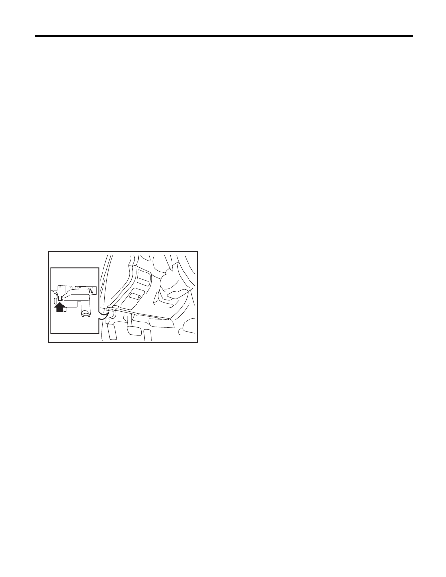
5) Connect SDI to data link connector located in the
lower portion of the instrument panel (on the driv-
er’s side).
CAUTION:
Do not connect scan tools other than the Suba-
ru Select Monitor.
6) Start the PC.
7) Turn the ignition switch to ON (engine OFF) and
run the “PC application for Subaru Select Monitor”.
8) On the «Main Menu» display, select the {Each
System Check}.
9) On the «System Selection Menu» display, select
the {Transmission Control System}.
10) After transmission type information pops up,
select [OK].
11) On the «Transmission Diagnosis» display, se-
lect the {Diagnostic Code(s) Display}.
12) On the «Diagnostic Code(s) Display» display,
select the {Temporary Diagnostic Code(s)} or
{Memorized Diagnostic Code(s)}.
NOTE:
• For detailed operation procedure, refer to the
“PC application help for Subaru Select Monitor”.
• For details concerning DTC, refer to “List of Diag-
nostic Trouble Code (DTC)”. <Ref. to 4AT(diag)-
30, List of Diagnostic Trouble Code (DTC).>
AT-04371
Нет комментариевНе стесняйтесь поделиться с нами вашим ценным мнением.
Текст