Subaru Legacy IV (2008 year). Service manual — part 696
4AT(diag)-5
General Description
AUTOMATIC TRANSMISSION (DIAGNOSTICS)
3. General Description
A: CAUTION
1. SUPPLEMENTAL RESTRAINT SYSTEM
“AIRBAG”
The airbag system wiring harness is routed near
the TCM.
CAUTION:
• All the airbag system wiring harnesses and
connectors are colored yellow. Do not use an
electric test equipment to check these circuits.
• Be careful not to damage the airbag system
wiring harness when performing diagnostics or
servicing the TCM.
2. MEASUREMENT
When measuring the voltage and resistance of the
ECM, TCM or each sensor, use a tapered pin with
a diameter of less than 0.64 mm (0.025 in) in order
to avoid poor contact. Do not insert a pin of more
than 0.65 mm (0.026 in) diameter.
B: INSPECTION
1. BATTERY
Measure the battery voltage and specific gravity of
the electrolyte.
Standard voltage: 12 V or more
Specific gravity: 1.260 or more
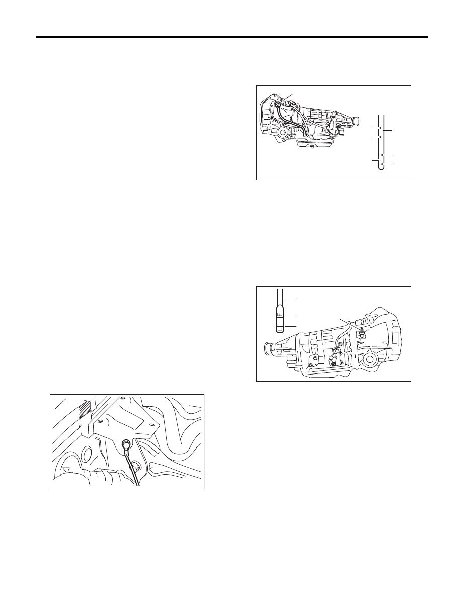
2. TRANSMISSION GROUND
Make sure that the ground terminal bolt is tightened
securely.
Chassis side
Tightening torque:
13 N·m (1.3 kgf-m, 9.4 ft-lb)
3. ATF LEVEL
Make sure that ATF level is the specified amount.
<Ref. to 4AT-26, INSPECTION, Automatic Trans-
mission Fluid.>
4. FRONT DIFFERENTIAL OIL LEVEL
Make sure the front differential oil level is the spec-
ified amount. <Ref. to 4AT-28, INSPECTION, Dif-
ferential Gear Oil.>
AT-01464
(A) Oil level gauge
(B) Inspection position when “HOT”
(C) Upper level
(D) Lower level
(E) Inspection position when “COLD”
(A) Oil level gauge
(B) Upper level
(C) Lower level
AT-04841
COLD
LF
HO
T
LF
(A)
(C)
(D)
(C)
(D)
(E)
(B)
AT-04863
(B)
(C)
(A)
(A)
4AT(diag)-6
General Description
AUTOMATIC TRANSMISSION (DIAGNOSTICS)
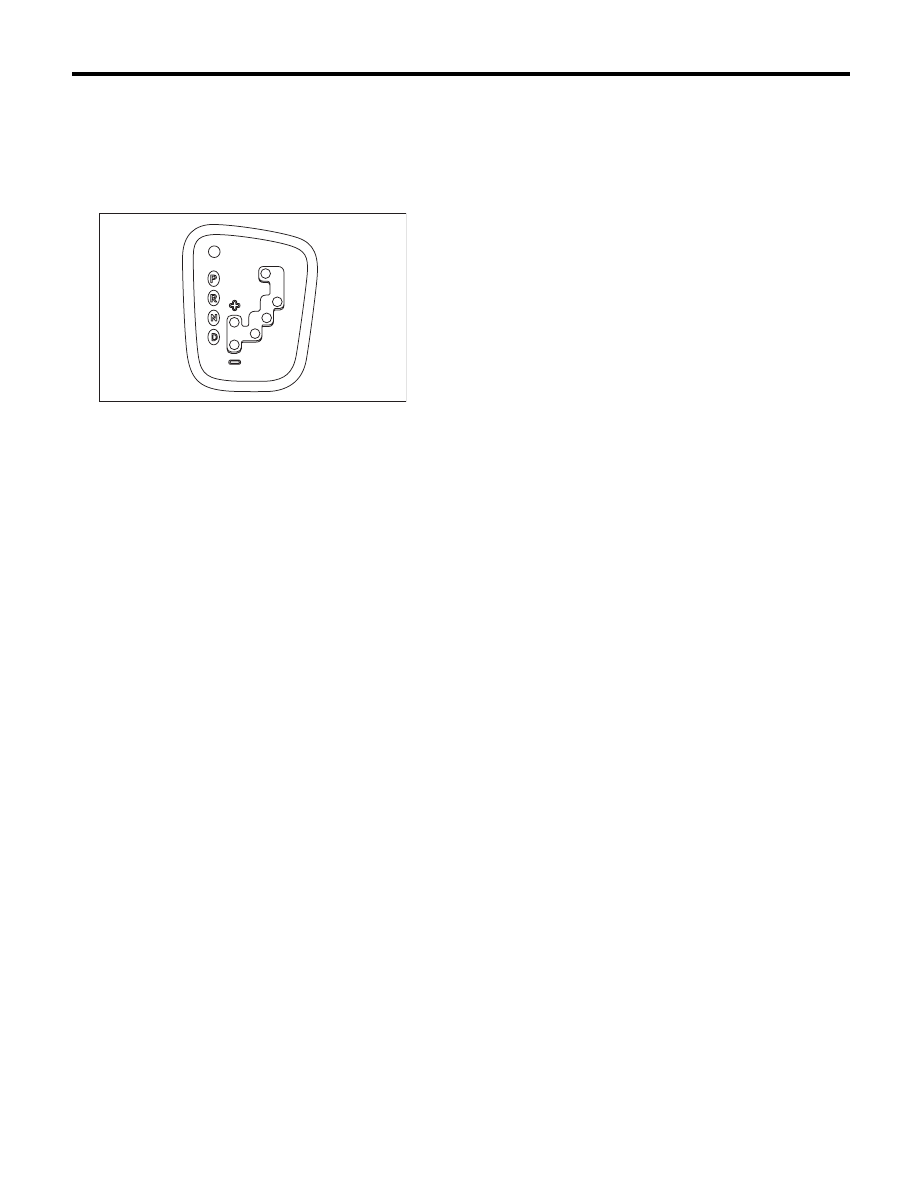
5. OPERATION OF SELECT LEVER
Make sure there is no noise, dragging or contact
pattern in each select lever range.
WARNING:
Stop the engine while checking operation of the
select lever.
AT-02048
4AT(diag)-7
General Description
AUTOMATIC TRANSMISSION (DIAGNOSTICS)
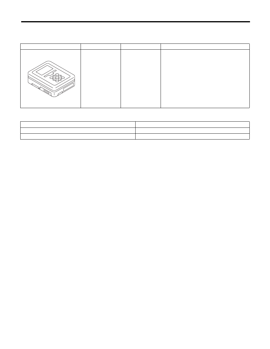
C: PREPARATION TOOL
1. SPECIAL TOOL
2. GENERAL TOOL
ILLUSTRATION
TOOL NUMBER
DESCRIPTION
REMARKS
1B022XU0
SUBARU SELECT
MONITOR III KIT
Used for troubleshooting the electrical system.
TOOL NAME
REMARKS
Circuit tester
Used for measuring resistance, voltage and current.
Oscilloscope
Used for measuring the sensor.
ST1B022XU0
4AT(diag)-8
Electrical Component Location
AUTOMATIC TRANSMISSION (DIAGNOSTICS)
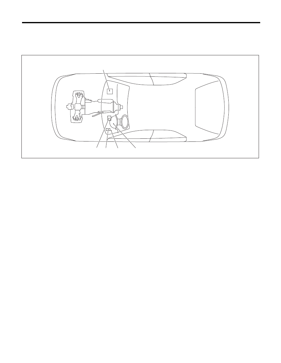
4. Electrical Component Location
A: LOCATION
1. CONTROL MODULE
(1)
Engine control module (ECM)
(3)
Transmission control module
(TCM)
(4)
Data link connector
(2)
ATF temperature warning light (AT
warning light)
(5)
Body integrated unit
(3)
(5)
(2)
(1)
AT-01873
(4)
Нет комментариевНе стесняйтесь поделиться с нами вашим ценным мнением.
Текст