Subaru Legacy IV (2008 year). Service manual — part 70
ME(H4SO)-76
Cylinder Block
MECHANICAL
(6) Install the service hole plug and gasket.
NOTE:
Use a new gasket.
Tightening torque:
70 N·m (7.1 kgf-m, 51.6 ft-lb)
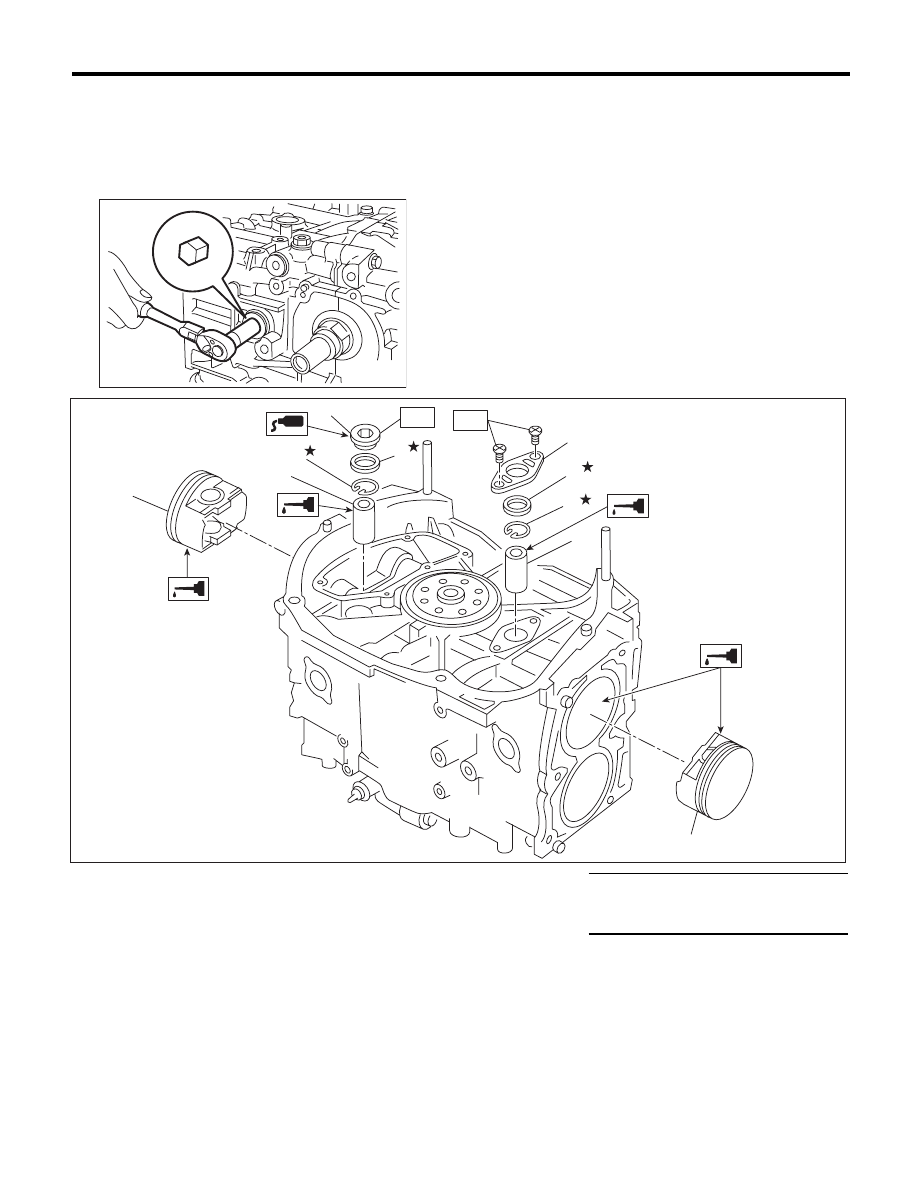
ME-00140
(1)
Piston
(5)
Service hole plug
Tightening torque:N·m (kgf-m, ft-lb)
(2)
Piston pin
(6)
Service hole cover
T1: 6.4 (0.7, 4.7)
(3)
Snap ring
(7)
O-ring
T2: 70 (7.1, 51.6)
(4)
Gasket
(2)
(3)
(1)
(2)
(6)
(3)
(7)
(4)
(5)
ME-02440
T2
T1
(1)
ME(H4SO)-77
Cylinder Block
MECHANICAL
(7) Set the parts so that the #3 and #4 cylinders
are on the upper side. Following the same pro-
cedures as used for #1 and #2 cylinders, install
the pistons and piston pins.
(8) Install the service hole cover.
NOTE:
Use new O-rings.
Tightening torque:
6.4 N·m (0.7 kgf-m, 4.7 ft-lb)
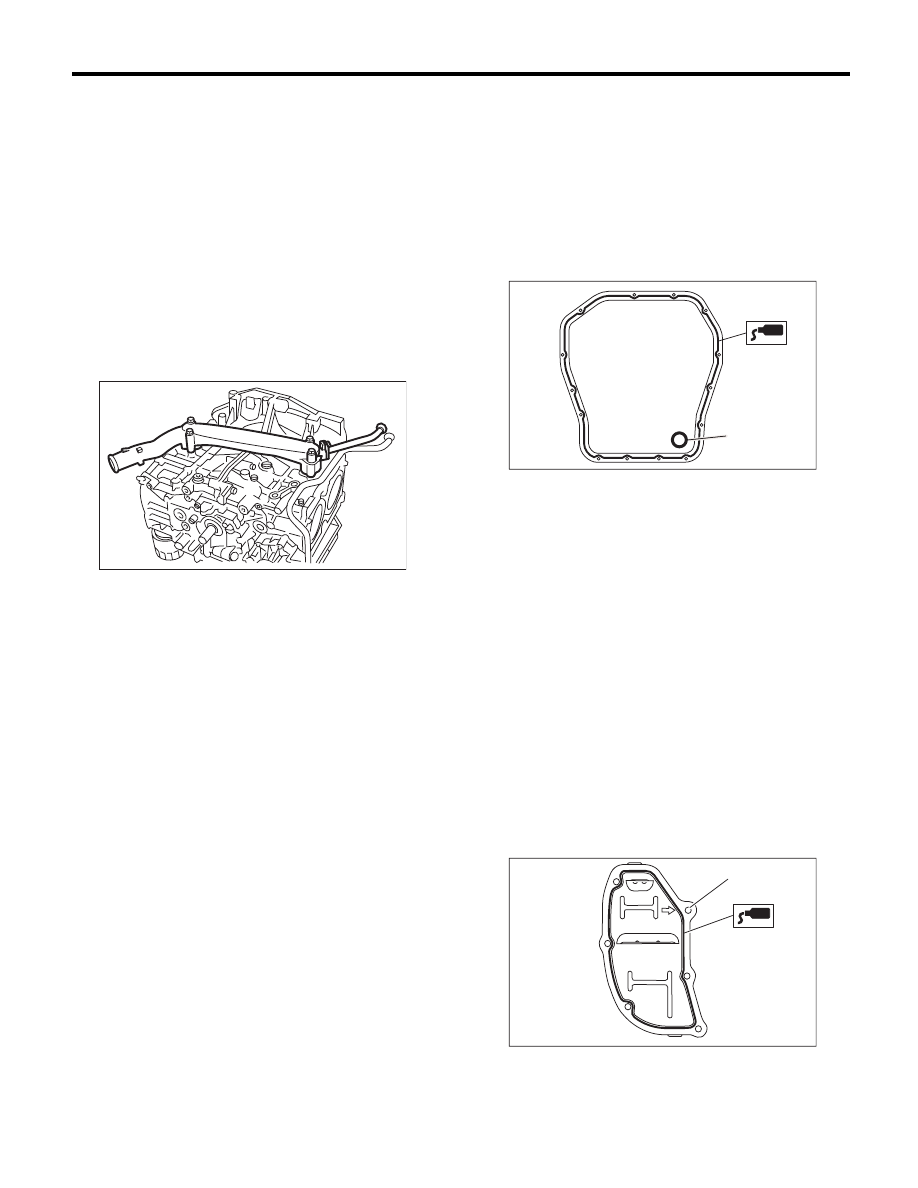
22) Install the water pipe assembly.
NOTE:
Use new O-rings.
Tightening torque:
6.4 N·m (0.7 kgf-m, 4.7 ft-lb)
23) Install the baffle plate.
Tightening torque:
6.4 N·m (0.7 kgf-m, 4.7 ft-lb)
24) Install the oil strainer.
NOTE:
Use new O-rings.
Tightening torque:
10 N·m (1.0 kgf-m, 7.4 ft-lb)
25) Tighten the oil strainer stay together with the
baffle plate.
Tightening torque:
6.4 N·m (0.7 kgf-m, 4.7 ft-lb)
26) Apply liquid gasket to the mating surfaces of oil
pan, and install the oil pan.
NOTE:
Install within 5 minutes after applying liquid gasket.
Liquid gasket:
THREE BOND 1217G (Part No. K0877Y0100)
or equivalent
Tightening torque:
5 N·m (0.5 kgf-m, 3.7 ft-lb)
27) Apply liquid gasket to the mating surfaces of
the oil separator cover and the threaded portion of
bolt (A) shown in the figure (when reusing the bolt),
and then install the oil separator cover.
NOTE:
• Install within 5 minutes after applying liquid gas-
ket.
• Use a new separator cover.
Liquid gasket:
• Mating surface
THREE BOND 1217G (Part No.
K0877Y0100) or equivalent
• (A) bolt thread (when reusing bolts)
THREE BOND 1324 (Part No. 004403042) or
equivalent
Tightening torque:
6.4 N·m (0.7 kgf-m, 4.7 ft-lb)
28) Install the flywheel. (MT model) <Ref. to CL-16,
INSTALLATION, Flywheel.>
ME-00300
(A) Gasket
LU-02353
(A)
ME-03333
(A)
ME(H4SO)-78
Cylinder Block
MECHANICAL
29) Install the clutch disc and cover. (MT model)
<Ref. to CL-13, INSTALLATION, Clutch Disc and
Cover.>
30) Use the ST to lock the crankshaft, and install
the drive plate. (AT model)
ST
498497100
CRANKSHAFT STOPPER
Tightening torque:
72 N·m (7.3 kgf-m, 53.1 ft-lb)
31) Install the oil pump.
(1) Install the front oil seal using the ST.
ST
499587100
OIL SEAL INSTALLER
NOTE:
Use a new front oil seal.
(2) Apply liquid gasket to the matching surface
of oil pump.
NOTE:
Install within 5 minutes after applying liquid gasket.
Liquid gasket:
THREE BOND 1217G (Part No. K0877Y0100)
or equivalent
(3) Apply a coat of engine oil to the inside of oil
seal.
(4) Install the oil pump to cylinder block. Be
careful not to damage the oil seal during instal-
lation.
NOTE:
• Make sure the oil seal lip is not folded.
• Align the flat surface of oil pump’s inner rotor with
crankshaft before installation.
• Use new O-rings and oil seals.
• Do not forget to assemble O-rings.
(5) Apply liquid gasket to the three bolts thread
shown in figure. (when reusing bolts)
Liquid gasket:
THREE BOND 1324 (Part No. 004403042) or
equivalent
Tightening torque:
T: 6.4 N·m (0.7 kgf-m, 4.7 ft-lb)
(A) O-ring
ME-00298
LU-00021
ST
ME-00165
(A)
ME-00312
LU-02103
T
ME(H4SO)-79
Cylinder Block
MECHANICAL
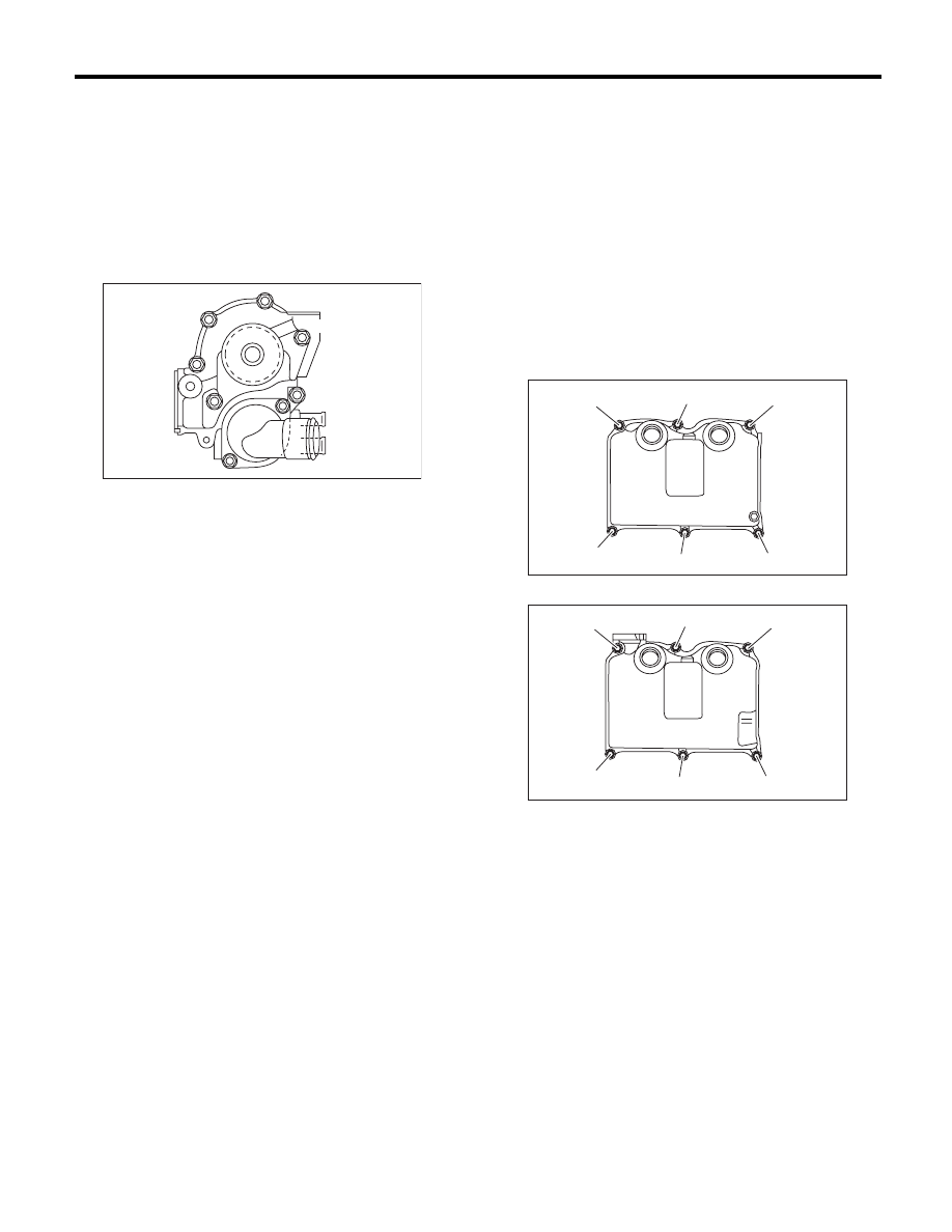
32) Install the water pump and gasket.
NOTE:
• When installing the water pump, tighten bolts in
two stages in alphabetical order as shown in the
figure.
• Use a new gasket.
Tightening torque:
First: 12 N·m (1.2 kgf-m, 8.9 ft-lb)
Second: 12 N·m (1.2 kgf-m, 8.9 ft-lb)
33) Install the water by-pass pipe for heater.
Tightening torque:
6.4 N·m (0.7 kgf-m, 4.7 ft-lb)
34) Install the oil filter. <Ref. to LU(H4SO)-23, IN-
STALLATION, Engine Oil Filter.>
35) Install the cylinder head. <Ref. to ME(H4SO)-
59, INSTALLATION, Cylinder Head.>
36) Install the generator and A/C compressor with
their brackets.
Tightening torque:
36 N·m (3.7 kgf-m, 26.6 ft-lb)
37) Install the crank sprocket. <Ref. to ME(H4SO)-
50, INSTALLATION, Crank Sprocket.>
38) Install the timing belt. <Ref. to ME(H4SO)-45,
INSTALLATION, Timing Belt.>
39) Adjust the valve clearance. <Ref. to
ME(H4SO)-28, ADJUSTMENT, Valve Clearance.>
40) Install the rocker cover.
(1) Install the rocker cover gasket to the rocker
cover.
NOTE:
Use a new rocker cover gasket.
(2) Temporarily tighten the bolts in alphabetical
order shown in the figure, tighten them in two
stages.
Tightening torque:
1st
6.4 N·m (0.7 kgf-m, 4.7 ft-lb)
2nd (only (a) and (b) are tightened)
6.4 N·m (0.7 kgf-m, 4.7 ft-lb)
RH side
LH side
41) Install the timing belt cover. <Ref. to
ME(H4SO)-43, INSTALLATION, Timing Belt Cov-
er.>
42) Install the crank pulley. <Ref. to ME(H4SO)-41,
INSTALLATION, Crank Pulley.>
43) Install the intake manifold. <Ref. to FU(H4SO)-
15, INSTALLATION, Intake Manifold.>
44) Install the V-belts. <Ref. to ME(H4SO)-39, IN-
STALLATION, V-belt.>
ME-02463
(F)
(E)
(D)
(C)
(B)
(A)
ME-02715
(a)
(b)
(c)
(d)
(e)
(f)
ME-02716
(a)
(b)
(c)
(d)
(e)
(f)
Нет комментариевНе стесняйтесь поделиться с нами вашим ценным мнением.
Текст