Subaru Legacy IV (2008 year). Service manual — part 755
5AT(diag)-35
Diagnostic Procedure with Diagnostic Trouble Code (DTC)
AUTOMATIC TRANSMISSION (DIAGNOSTICS)
14.Diagnostic Procedure with Diagnostic Trouble Code (DTC)
A: DTC P0705 TRANSMISSION RANGE SENSOR CIRCUIT (PRNDL INPUT)
DTC DETECTING CONDITION:
The inhibitor switch is open or short.
TROUBLE SYMPTOM:
• Shift characteristics are erroneous.
• Shift indicator light does not match with select lever.
• Shift indicator light does not illuminate.
• N-D, N-R shock occur.
5AT(diag)-36
Diagnostic Procedure with Diagnostic Trouble Code (DTC)
AUTOMATIC TRANSMISSION (DIAGNOSTICS)
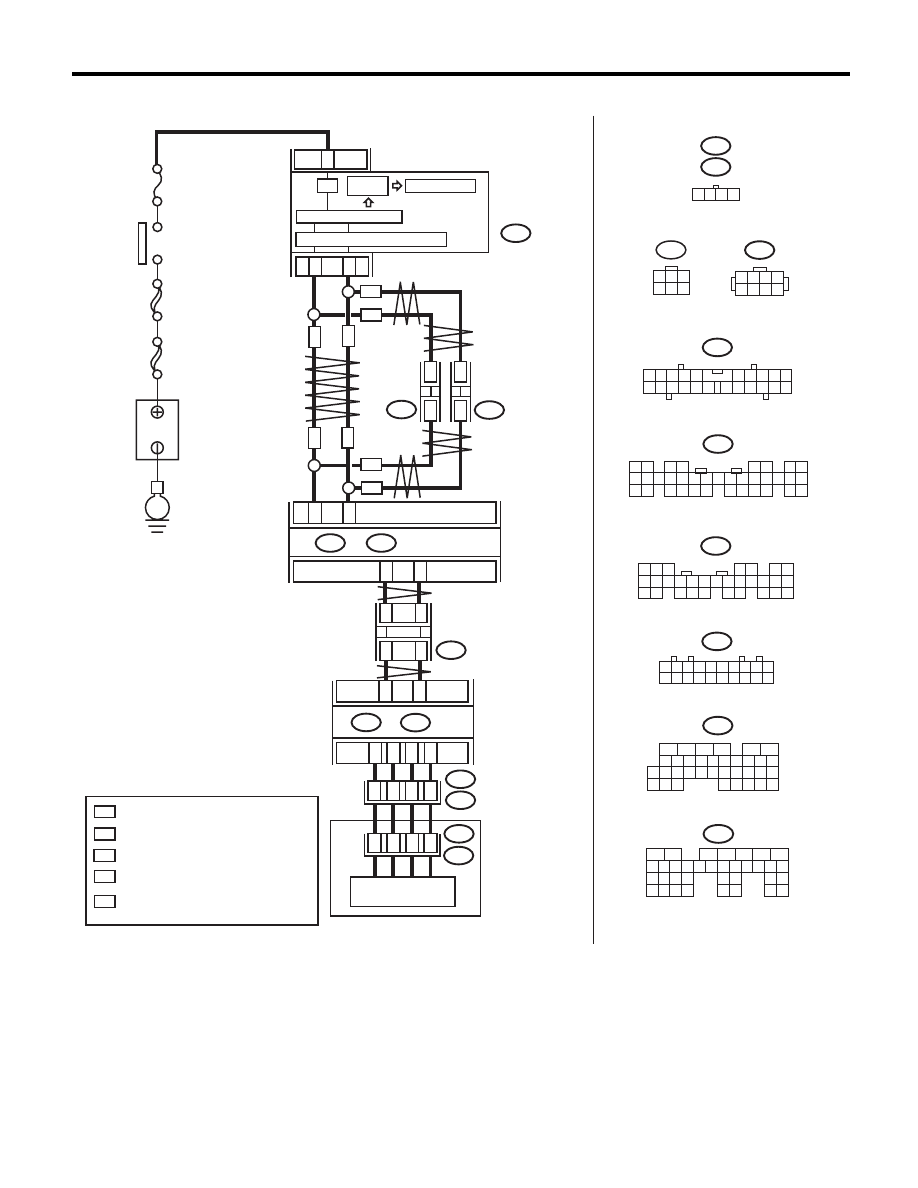
WIRING DIAGRAM:
AT-04894
3
21
22
i10
A26
A27
B20
B30
TCM
B55
i10
i84
B280
2
1
3 4
6 7 8 9 10
22
21
20
19
18
17
16
15
14
13
12
11
5
8
7
6
5
4
3
2
1
22 23
21
20
19
16
15
14
13
12
11
10
9
34 35
33
32
17
30
18
31
29
28
27
26
25
24
8
7
6
5
4
3
2
1
22
23
21
20
19
16
15
14
13
12
11
10
9
17
30
18
29
28
27
26
25
24
A:
B:
i107
i106
1 2 3 4 5 6 7 8 9 10
11 12 13 14 15 16 17 18 19 20
1
*
2
*
1
*
2
*
1 2 3 4
MAIN SBF
SBF-6
No.
5
E
B365
A:
B54
B:
B21
B20
T14
1
2
3
4
A11
A10
A9
A
8
6
2
3
5
T3
B12
B54
A:
B:
B55
5
6
7
8
2
1
9
4
3
10
24
22 23
25
11 12 13 14 15
26 27
28
16 17 18 19
20 21
29 30 31
32 33
34 35
5
6
7 8
2
1
9
4
3
10
24
22 23
25
11 12 13 14 15
26 27
28
16
17 18 19 20 21
33 34
29
32
30
31
35
T14
1
3
4 5 6
2
B12
8
7
6
5
4
3
2
1
T24
i84
A:
B280
B:
B365
:
:
1
*
2
*
:
*
:
WN
:
ON
WN
WN
ON
i107
i106
*
*
*
*
ON
WN
WN
ON
ON
I / F
IGNITION
SWITCH
B
A
TTER
Y
COMBINATION
METER
MICRO COMPUTER
DRIVE
CIRCUIT
CAN TRANSCEIVER & RECEIVER
CAN
JOINT
CONNECTOR
CAN
JOINT
CONNECTOR
CAN
JOINT
CONNECTOR
BODY
INTEGRATED UNIT
LCD FULL DOT
INHIBITOR SWITCH
CONTROL VALVE BODY
WITH NAVIGATION
WITHOUT NAVIGATION
TERMINAL No. OPTIONAL ARRANGEMENT
AMONG 1, 2, 3, 11, 12 AND 13
TERMINAL No. OPTIONAL ARRANGEMENT
TERMINAL No. OPTIONAL ARRANGEMENT
AMONG 8, 9, 10, 18, 19 AND 20

5AT(diag)-37
Diagnostic Procedure with Diagnostic Trouble Code (DTC)
AUTOMATIC TRANSMISSION (DIAGNOSTICS)
Step
Check
Yes
No
1
CHECK DTC OF TCM.
Is DTC of AT CAN communica-
tion circuit displayed?
Perform the diag-
nosis according to
DTC.
Go to step 2.
2
CHECK INHIBITOR SWITCH.
1) Shift the select lever to “P” range.
2) Check input signal of inhibitor SW 1 — 4
monitor using Subaru Select Monitor.
Is all displayed High?
Go to step 4.
Go to step 3.
3
CHECK HARNESS CONNECTOR BETWEEN
TCM AND TRANSMISSION.
1) Turn the ignition switch to OFF.
2) Disconnect the connectors from TCM and
transmission.
3) Measure the resistance between TCM con-
nector and chassis ground about the item which
indicated Low on step 2.
Connector & terminal
(B54) No. 8 — Chassis ground:
(B54) No. 9 — Chassis ground:
(B54) No. 10 — Chassis ground:
(B54) No. 11 — Chassis ground:
Is the resistance 1 M
: or
more?
Go to step 6.
Repair the short
circuit of harness
between TCM con-
nector and chassis
ground.
4
CHECK INHIBITOR SWITCH.
1) Shift the select lever to “D” range.
2) Check input signal of inhibitor SW 1 — 4
monitor using Subaru Select Monitor.
Is all displayed Low?
Go to step 6.
Go to step 5.
5
CHECK HARNESS CONNECTOR BETWEEN
TCM AND TRANSMISSION.
1) Turn the ignition switch to OFF.
2) Disconnect the connectors from TCM and
transmission.
3) Measure the resistance of harness between
TCM and transmission connector about the
item which indicated High on step 4.
Connector & terminal
(B54) No. 8 — (B12) No. 4:
(B54) No. 9 — (B12) No. 3:
(B54) No. 10 — (B12) No. 2:
(B54) No. 11 — (B12) No. 1:
Is the resistance less than 1
:? Go to step 6.
Repair the open
circuit of harness
between TCM con-
nector and trans-
mission connector.
6
CHECK INPUT SIGNAL FOR TCM USING
CIRCUIT TESTER.
1) Turn the ignition switch to OFF.
2) Disconnect the transmission connector
(B12).
3) Connect the TCM connector.
4) Turn the ignition switch to ON.
5) Measure the voltage between TCM termi-
nals.
Connector & terminal
(B54) No. 8 (+) — (B55) No. 23 (–):
(B54) No. 9 (+) — (B55) No. 23 (–):
(B54) No. 10 (+) — (B55) No. 23 (–):
(B54) No. 11 (+) — (B55) No. 23 (–):
Is the voltage of inhibitor SW 1 —
4 between 4 — 6 V?
Go to step 8.
Go to step 7.
7
CHECK TCM I/O SIGNAL.
Check the power supply and ground I/O signals.
<Ref. to 5AT(diag)-14, ELECTRICAL SPECIFI-
CATION, Transmission Control Module (TCM) I/
O Signal.>
Is TCM I/O signal OK?
Replace the TCM.
<Ref. to 5AT-60,
Transmission Con-
trol Module
(TCM).>
Repair the open or
short circuit for
power supply and
ground.

5AT(diag)-38
Diagnostic Procedure with Diagnostic Trouble Code (DTC)
AUTOMATIC TRANSMISSION (DIAGNOSTICS)
8
CHECK HARNESS CONNECTOR BETWEEN
TRANSMISSION AND CONTROL VALVE
BODY.
1) Turn the ignition switch to OFF.
2) Disconnect the connector from transmis-
sion.
3) Remove the transmission connector from
bracket.
4) Lift up the vehicle.
NOTE:
Raise all wheels off the floor.
5) Drain the ATF.
CAUTION:
Do not drain ATF until it cools down.
6) Remove the oil pan, and disconnect the
connector from control valve body connector.
7) Measure the resistance between transmis-
sion connector and control valve body connec-
tor.
Connector & terminal
(T3) No. 4 — (T14) No. 2:
(T3) No. 3 — (T14) No. 3:
(T3) No. 2 — (T14) No. 5:
(T3) No. 1 — (T14) No. 6:
Is the resistance less than 1
:? Go to step 9.
Repair the open
circuit of harness
between control
valve body con-
nector and trans-
mission connector.
9
CHECK HARNESS CONNECTOR BETWEEN
TRANSMISSION AND CONTROL VALVE
BODY.
Measure the resistance between transmission
ground and control valve body connector.
Connector & terminal
(T14) No. 2 — Transmission ground:
(T14) No. 3 — Transmission ground:
(T14) No. 5 — Transmission ground:
(T14) No. 6 — Transmission ground:
Is the resistance 1 M
: or
more?
Go to step 10.
Repair the short
circuit of harness
between control
valve body con-
nector and trans-
mission connector.
10
CHECK POOR CONTACT.
Is there any poor contact in
inhibitor SW 1 — 4 monitor cir-
cuit?
Repair the poor
contact.
Replace the con-
trol valve body.
<Ref. to 5AT-57,
Control Valve
Body.>
Step
Check
Yes
No
Нет комментариевНе стесняйтесь поделиться с нами вашим ценным мнением.
Текст