Subaru Legacy IV (2008 year). Service manual — part 753
5AT(diag)-27
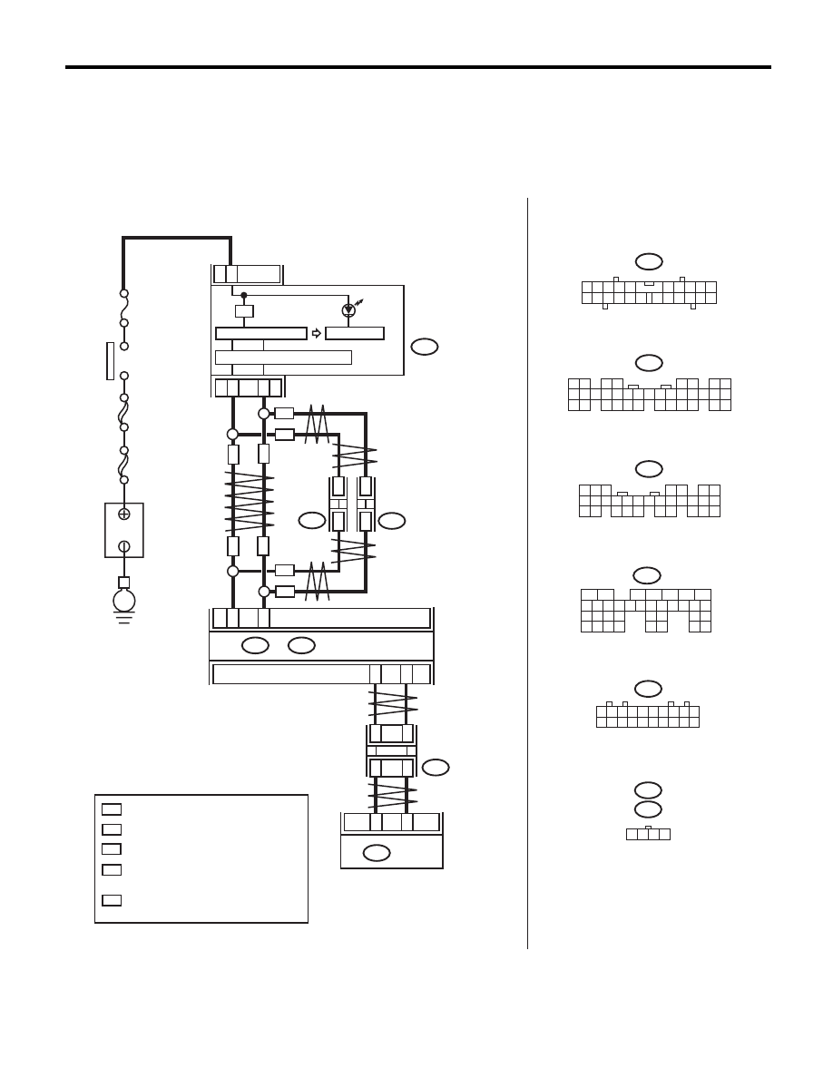
AT OIL TEMP Warning Light Display
AUTOMATIC TRANSMISSION (DIAGNOSTICS)
B: INSPECTION
DIAGNOSIS:
AT OIL TEMP light circuit is open or shorted.
TROUBLE SYMPTOM:
When the ignition switch is turned to ON (engine OFF), AT OIL TEMP light does not illuminate.
WIRING DIAGRAM:
AT-04892
3
21
22
i10
i84
A:
B280
B:
A26
A27
B20
B30
21
20
TCM
B55
i10
i84
B280
2
1
3 4
6 7 8 9 10
22
21
20
19
18
17
16
15
14
13
12
11
5
8
7
6
5
4
3
2
1
22 23
21
20
19
16
15
14
13
12
11
10
9
34 35
33
32
17
30
18
31
29
28
27
26
25
24
8
7
6
5
4
3
2
1
22
23
21
20
19
16
15
14
13
12
11
10
9
17
30
18
29
28
27
26
25
24
A:
B:
B365
i107
i106
1 2 3 4 5 6 7 8 9 10
11 12 13 14 15 16 17 18 19 20
1
*
2
*
1
*
2
*
:
:
1
*
2
*
:
*
1 2 3 4
MAIN SBF
SBF-6
No.
5
E
B365
B55
5
6
7
8
2
1
9
4
3
10
24
22 23
25
11 12 13 14 15
26 27
28
16 17 18 19
20 21
29 30 31
32 33
34 35
WITH NAVIGATION
WITHOUT NAVIGATION
:
WN
:
ON
WN
WN
ON
i107
i106
*
*
*
CAN
JOINT
CONNECTOR
*
ON
WN
WN
ON
ON
BODY INTEGRATED UNIT
IGNITION
SWITCH
B
A
TTER
Y
MICRO COMPUTER
CAN TRANSCEIVER & RECEIVER
COMBINATION
METER
CAN
JOINT
CONNECTOR
CAN
JOINT
CONNECTOR
TERMINAL No. OPTIONAL ARRANGEMENT
AMONG 1, 2, 3, 11, 12 AND 13
TERMINAL No. OPTIONAL ARRANGEMENT
TERMINAL No. OPTIONAL ARRANGEMENT
AMONG 8, 9, 10, 18, 19 AND 20
AT OIL
TEMP

5AT(diag)-28
AT OIL TEMP Warning Light Display
AUTOMATIC TRANSMISSION (DIAGNOSTICS)
Step
Check
Yes
No
1
CHECK AT OIL TEMP LIGHT.
Turn the ignition switch to ON.
Does the AT OIL TEMP light
illuminate?
Go to step 2.
Perform the self-
diagnosis of com-
bination meter.
2
CHECK AT OIL TEMP LIGHT.
After the ignition switch is ON, wait for at least 2
seconds.
Does the AT OIL TEMP light
illuminate?
Go to step 3.
Go to step 4.
3
CHECK AT OIL TEMP LIGHT.
Start the engine.
Does the AT OIL TEMP light go
off?
Normal. Go back to
Basic Diagnostic
Procedure. <Ref.
to 5AT(diag)-2,
Basic Diagnostic
Procedure.>
Go to step 7.
4
CHECK SUBARU SELECT MONITOR COM-
MUNICATION.
Connect the Subaru Select Monitor to data link
connector.
Is the communication between
Subaru Select Monitor and
TCM normal?
Go to step 5.
Check the power
supply ground cir-
cuit of TCM and
Subaru Select
Monitor communi-
cation. <Ref. to
5AT(diag)-29,
Diagnostic Proce-
dure for Subaru
Select Monitor
Communication.>
5
CHECK TCM.
Display the current data of TCM using Subaru
Select Monitor.
Is the “Diagnosis Light” output
signal “ON”?
Go to step 6.
Replace the TCM.
<Ref. to 5AT-60,
Transmission Con-
trol Module
(TCM).>
6
CHECK BODY INTEGRATED UNIT.
Display the current data of body integrated unit
using Subaru Select Monitor. <Ref. to
LAN(diag)-12, OPERATION, Subaru Select
Monitor.>
Does the “AT OIL TEMP light”
input signal “Illuminate”?
Replace the com-
bination meter
assembly. <Ref. to
IDI-22, Combina-
tion Meter.>
Check DTC of
body integrated
unit. <Ref. to
LAN(diag)-12,
OPERATION, Sub-
aru Select Moni-
tor.>
7
CHECK TCM.
1) Start the engine.
2) Display the current data of TCM using Sub-
aru Select Monitor. <Ref. to 5AT(diag)-18,
OPERATION, Subaru Select Monitor.>
Is the “Diagnosis Light” output
signal “ON”?
Replace the TCM.
<Ref. to 5AT-60,
Transmission Con-
trol Module
(TCM).>
Go to step 8.
8
CHECK BODY INTEGRATED UNIT.
Display the current data of body integrated unit
using Subaru Select Monitor. <Ref. to
LAN(diag)-12, OPERATION, Subaru Select
Monitor.>
Does the “AT OIL TEMP light”
input signal “Illuminate”?
Check DTC of
body integrated
unit. Perform the
diagnosis accord-
ing to DTC. <Ref.
to LAN(diag)-12,
OPERATION, Sub-
aru Select Moni-
tor.>
Perform the self-
diagnosis of com-
bination meter.
<Ref. to IDI-5,
INSPECTION,
Combination Meter
System.>
5AT(diag)-29
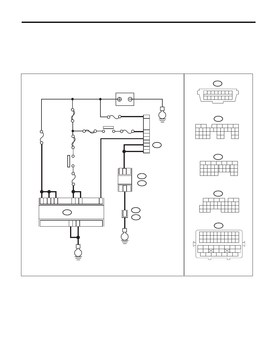
Diagnostic Procedure for Subaru Select Monitor Communication
AUTOMATIC TRANSMISSION (DIAGNOSTICS)
12.Diagnostic Procedure for Subaru Select Monitor Communication
A: COMMUNICATION FOR INITIALIZING IMPOSSIBLE
DIAGNOSIS:
Defective harness connector
TROUBLE SYMPTOM:
Subaru Select Monitor communication failure
WIRING DIAGRAM:
AT-04893
B40
M/B No.
12
16
5
7
4
E
1 2 3 4 5 6 7 8
9 10 11 12 13 14 15 16
5
6
7
2
1
3
4
29
10 11 12 13 14 15
25
24
16
30
9
8
17 18 19
20
28
21 22 23
32
31
26 27
33
34 35
No. 13
MAIN SBF
SBF-6
F/B No.
12
B40
B55
TCM
25
19
18
8
E
27
26
23
22
B55
E
B134
A:
B136
C:
ECM
C6
A5
36
B21
C: B136
16
10 11 12 13 14 15
25
24
30
9
8
7
17 18 19 20
28
21 22 23
29
32
31
1
2
3
4
5
6
27
26
33 34 35
8
5
6
10 11 12 13 14 15
7
2
1
3
4
16
30
19 20
22
28 29
9
17
18
25
21
23 24
32
31
26 27
33 34
B134
A:
1 2 3 4 5 6 7 8 9 10 11
12 13 14 15 16 17 18 19 20 21 22
23 24 25 26 27 28 29 30 31 32 33
34
35
42
43
36
37
38
39
48
49
50
51
52
53
54
40
41
44
45
46
47
B21
E2
8
SBF-8
No. 4
IG2 RELAY
BATTERY
DATA LINK
CONNECTOR
IGNITION
SWITCH

5AT(diag)-30
Diagnostic Procedure for Subaru Select Monitor Communication
AUTOMATIC TRANSMISSION (DIAGNOSTICS)
Step
Check
Yes
No
1
CHECK SUBARU SELECT MONITOR POW-
ER SUPPLY CIRCUIT.
Measure the voltage between data link connec-
tor and chassis ground.
Connector & terminal
(B40) No. 16 (+) — Chassis ground (–):
Is the voltage 10 V or more?
Go to step 2.
Repair harness
connector between
the battery and
data link connec-
tor, and poor con-
tact of the
connector.
2
CHECK SUBARU SELECT MONITOR
GROUND CIRCUIT.
Measure the resistance of harness between
data link connector and chassis ground.
Connector & terminal
(B40) No. 4 — Chassis ground:
(B40) No. 5 — Chassis ground:
Is the resistance less than 1
:? Go to step 3.
Repair the open
circuit of harness
between data link
connector and
ground terminal,
and poor contact of
connector.
3
CHECK COMMUNICATION OF SUBARU SE-
LECT MONITOR.
1) Turn the ignition switch to ON.
2) Using the Subaru Select Monitor, check
whether communication to the transmission
system can be executed normally.
Is the name of system dis-
played on Subaru Select Moni-
tor?
Go to step 8.
Go to step 4.
4
CHECK COMMUNICATION OF SUBARU SE-
LECT MONITOR.
1) Turn the ignition switch to OFF.
2) Disconnect the TCM connector.
3) Turn the ignition switch to ON.
4) Check whether communication to engine
system can be executed normally.
Is the name of system dis-
played on Subaru Select Moni-
tor?
Go to step 6.
Go to step 5.
5
CHECK COMMUNICATION OF SUBARU SE-
LECT MONITOR.
1) Turn the ignition switch to OFF.
2) Connect the TCM connector.
3) Disconnect the connector from ECM.
4) Turn the ignition switch to ON.
5) Check whether communication to transmis-
sion system can be executed normally.
Is the name of system dis-
played on Subaru Select Moni-
tor?
Inspect the ECM.
Go to step 6.
6
CHECK HARNESS CONNECTOR BETWEEN
EACH CONTROL MODULE AND DATA LINK
CONNECTOR.
1) Turn the ignition switch to OFF.
2) Disconnect the TCM and ECM connector.
3) Measure the resistance between TCM con-
nector and chassis ground.
Connector & terminal
(B40) No. 7 — Chassis ground:
Is the resistance 1 M
: or
more?
Go to step 7.
Check harness
and connector
between each con-
trol module and
data link connec-
tor.
7
CHECK OUTPUT SIGNAL OF TCM.
1) Turn the ignition switch to ON.
2) Measure the voltage between TCM and
chassis ground.
Connector & terminal
(B40) No. 7 (+) — Chassis ground (–):
Is the voltage 1 V or more?
Check harness
and connector
between each con-
trol module and
data link connec-
tor.
Go to step 8.
8
CHECK HARNESS CONNECTOR BETWEEN
TCM AND DATA LINK CONNECTOR.
Measure the resistance between TCM connec-
tor and data link connector.
Connector & terminal
(B55) No. 8 — (B40) No. 7:
Is the resistance less than 1
:? Go to step 9.
Repair the harness
and connector
between TCM and
data link connec-
tor.
9
CHECK INSTALLATION OF TCM CONNEC-
TOR.
Turn the ignition switch to OFF.
Is TCM connector connected to
TCM?
Go to step 10.
Connect the TCM
connector to TCM.
Нет комментариевНе стесняйтесь поделиться с нами вашим ценным мнением.
Текст