Subaru Legacy IV (2008 year). Service manual — part 894
DS-21
Rear Hub Unit Bearing
DRIVE SHAFT SYSTEM
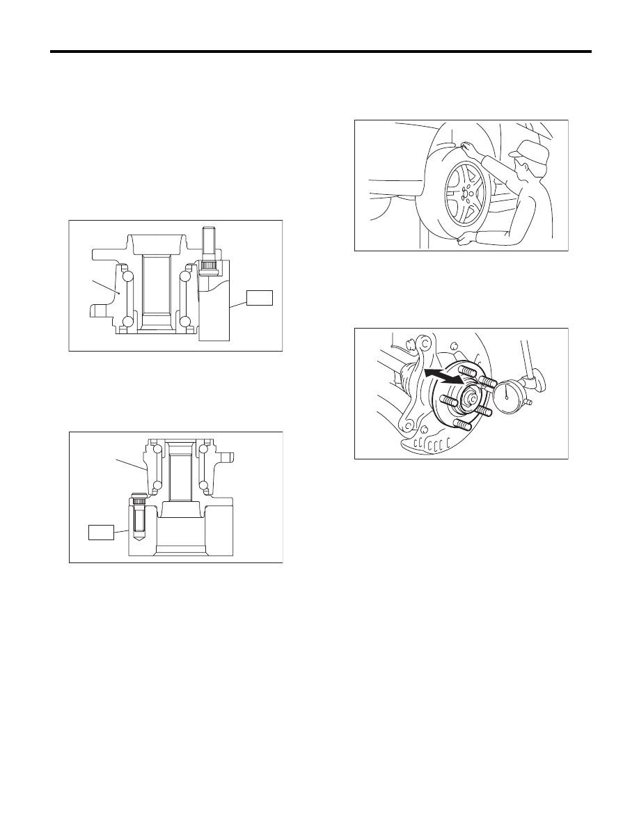
C: DISASSEMBLY
Using the ST and a hydraulic press, push out the
hub bolts.
ST
28399AG000 HUB STAND
CAUTION:
• Be careful not to hammer the hub bolts. This
may deform the hub.
• Do not reuse the hub bolt.
NOTE:
Since the hub unit bearing can not be disassem-
bled, only hub bolts can be removed.
D: ASSEMBLY
1) Attach the hub to the ST securely.
ST
927080000
HUB STAND
2) Using a press, press the new hub bolts until their
seating surfaces contact the hub.
NOTE:
Use the 12 mm (0.47 in) dia. holes in the HUB
STAND to prevent bolts from tilting.
E: INSPECTION
1) Moving the rear tire up and down by hand, check
there is no backlash in bearing, and check the
wheel rotates smoothly.
2) Inspect the lean of axis direction using a dial
gauge. Replace the hub bearing if the play exceeds
the limit value.
Service limit:
Maximum: 0.05 mm (0.0020 in)
(1) Rear hub unit bearing
(1) Rear hub unit bearing
DS-00254
ST
(1)
DS-00255
ST
(1)
DS-00183
DS-00062
DS-22
Front Drive Shaft
DRIVE SHAFT SYSTEM
6. Front Drive Shaft
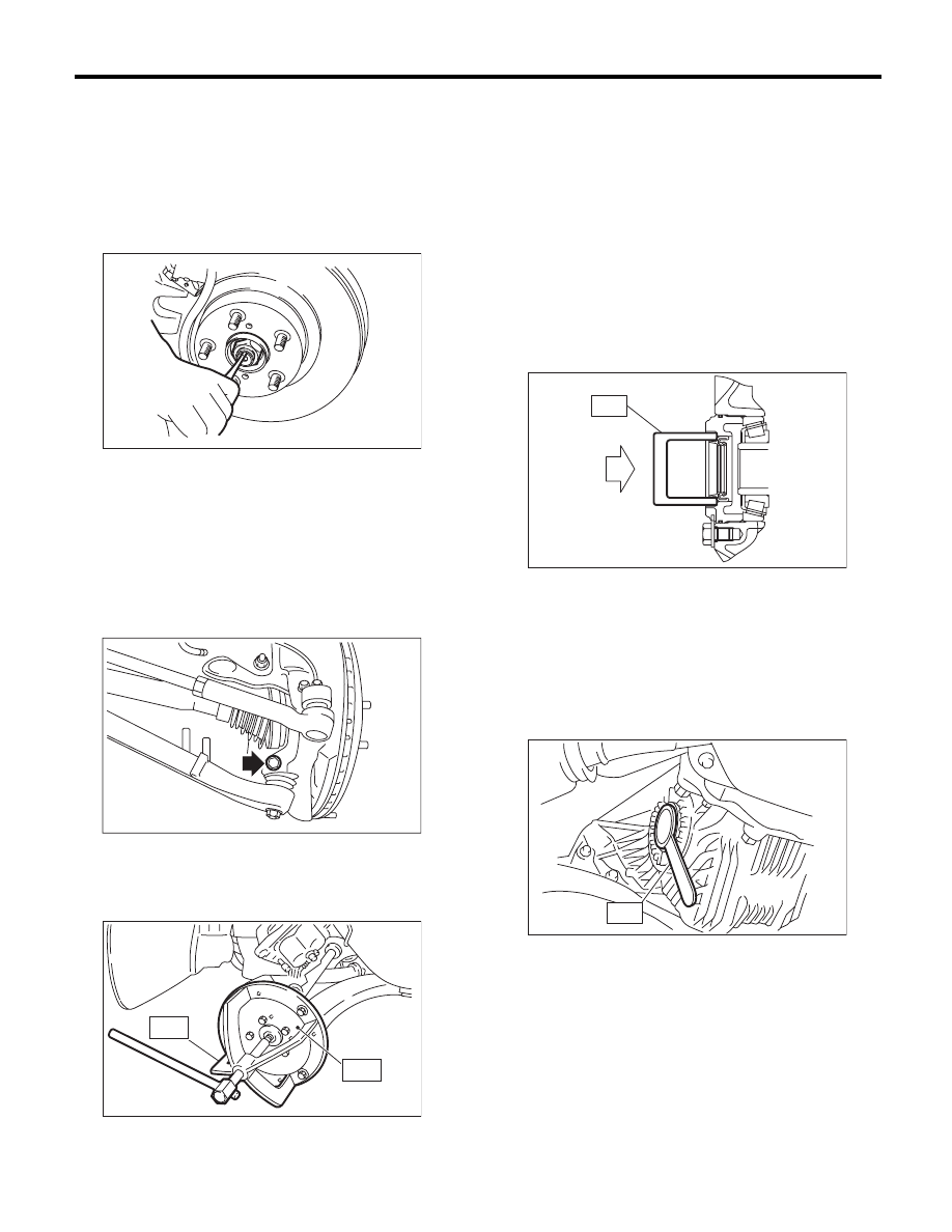
A: REMOVAL
1) Disconnect the ground cable from the battery.
2) Lift up the vehicle, and remove the front wheels.
3) Drain the transmission gear oil. (MT model)
4) Drain the differential gear oil. (AT model)
5) Lift the crimped section of axle nut.
6) Remove the axle nut using a socket wrench
while depressing the brake pedal.
CAUTION:
Remove the wheel before loosening the axle
nut. Failure to follow this rule may damage the
wheel bearings.
7) Remove the stabilizer link from front arm.
8) Disconnect the front arm ball joint from the hous-
ing.
9) Remove the front drive shaft assembly. If it is
hard to remove, use ST1 and ST2.
ST1
926470000
AXLE SHAFT PULLER
ST2
28099PA110 AXLE SHAFT PULLER PLATE
10) Using a bar, remove the front drive shaft from
transmission.
CAUTION:
Be careful not to allow the bar to damage holder
area.
B: INSTALLATION
1) Using the ST, replace the differential side retain-
er oil seal with a new seal.
ST
18675AA000
DIFFERENTIAL SIDE OIL
SEAL INSTALLER
NOTE:
After pulling out the drive shaft, be sure to replace
with a new oil seal.
2) Insert the EBJ into hub splines.
3) Draw the drive shaft into specified position.
CAUTION:
Do not hammer drive shaft when installing it.
4) Tighten the axle nut temporarily.
5) Using the ST, install the front drive shaft to trans-
mission.
ST
28399SA010
OIL SEAL PROTECTOR
6) Connect the front arm ball joint to the housing.
Tightening torque:
50 N·m (5.1 kgf-m, 36.9 ft-lb)
7) Install the stabilizer link.
Tightening torque:
45 N·m (4.6 kgf-m, 33.2 ft-lb)
CAUTION:
Be sure to use a new self-locking nut.
DS-00038
FS-00106
DS-00145
ST2
ST1
ST
MT-00103
AT-00110
ST
DS-23
Front Drive Shaft
DRIVE SHAFT SYSTEM
8) While depressing the brake pedal, tighten a new
axle nut to the specified torque and lock it securely.
Tightening torque:
220 N·m (22.4 kgf-m, 162 ft-lb)
CAUTION:
• Install the wheel after installation of axle nut.
Failure to follow this rule may damage the
wheel bearing.
• Be sure to tighten axle nut to specified
torque. Do not overtighten it as this may dam-
age the wheel bearing.
9) After tightening axle nut, lock it securely.
10) Fill the transmission gear oil. (MT model)
11) Fill the differential gear oil. (AT model)
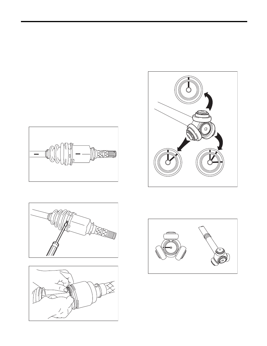
C: DISASSEMBLY
1) Place alignment marks on the shaft and outer
race.
2) Remove the PTJ boot band and boot.
CAUTION:
Be careful not to damage the boot.
3) Remove the snap ring from PTJ outer race.
4) Remove the PTJ outer race from shaft assem-
bly.
5) Wipe off grease.
CAUTION:
The grease is a special type of grease. Do not
mix with other grease.
6) Place alignment marks on the roller kit and trun-
nion.
7) Remove the roller kit from trunnion.
CAUTION:
Be careful with the roller kit position.
8) Place alignment marks on the trunnion and
shaft.
DS-00106
DS-00107
DS-00108
DS-00109
DS-00110
DS-24
Front Drive Shaft
DRIVE SHAFT SYSTEM
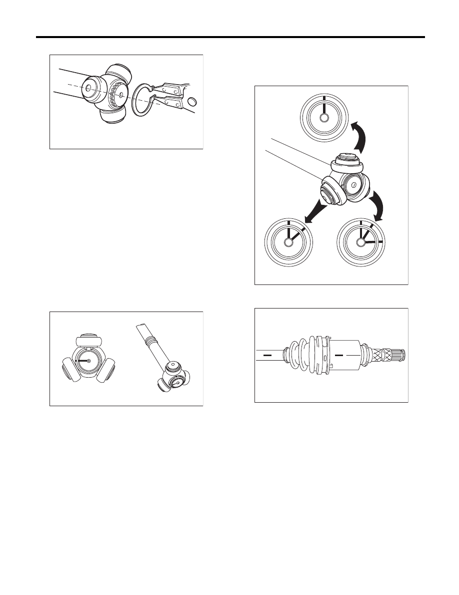
9) Remove the snap ring and trunnion.
CAUTION:
Be sure to wrap shaft splines with vinyl tape to
protect the boot from scratches.
10) Remove the PTJ boot.
NOTE:
The BJ is a non-disassembly part, so the axle dis-
assembly stops here.
D: ASSEMBLY
NOTE:
Use specified grease.
PTJ side:
NKG302
1) Place the PTJ boot at the center of shaft.
2) Align alignment marks and install the trunnion on
the shaft.
3) Install the snap ring to shaft.
CAUTION:
Confirm that the snap ring is completely fitted
in shaft groove.
4) Fill 100 to 110 g (3.53 to 3.88 oz) of specified
grease into the interior of PTJ outer race.
5) Apply a thin coat of specified grease to the roller
kit and trunnion.
6) Align alignment marks on roller kit and trunnion
and install the roller kit.
CAUTION:
Be careful with the roller kit position.
7) Align the alignment marks of the shaft and outer
race, and install the outer race.
8) Install the snap ring in the groove on PTJ outer
race.
CAUTION:
Pull the shaft lightly and assure that the snap
ring is completely fitted in the groove.
9) Apply an even coat of the specified grease 30 to
40 g (1.06 to 1.41 oz) to the entire inner surface of
boot.
10) Install the PTJ boot taking care not to twist it.
CAUTION:
• The large end of PTJ boot and the boot
groove shall be cleaned completely so as to be
free from grease and other substances.
• When installing PTJ boot, position outer race
of PTJ at center of its travel.
DS-00111
DS-00110
DS-00109
DS-00106
Нет комментариевНе стесняйтесь поделиться с нами вашим ценным мнением.
Текст