Subaru Legacy IV (2008 year). Service manual — part 893
DS-17
Front Hub Unit Bearing
DRIVE SHAFT SYSTEM
4. Front Hub Unit Bearing
A: REMOVAL
1) Disconnect the ground cable from the battery.
2) Lift up the vehicle, and remove the front wheels.
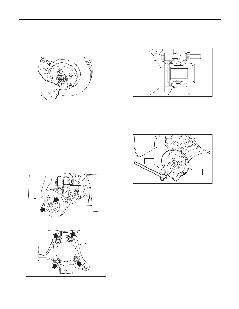
3) Lift the crimped section of axle nut.
4) Remove the axle nut using a socket wrench
while depressing the brake pedal.
CAUTION:
Remove the wheel before loosening the axle
nut. Failure to follow this rule may damage the
wheel bearings.
5) Remove the disc brake caliper from the housing,
and suspend it from strut using a wire.
6) Remove the disc rotor from the hub.
NOTE:
If it is difficult to remove the disc rotor from the hub,
drive the 8 mm bolt into the threaded end of rotor,
and then remove the rotor.
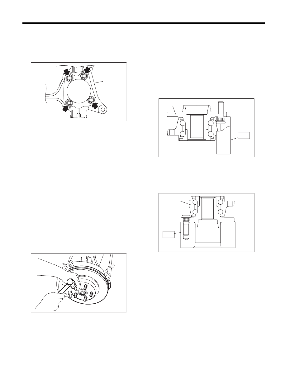
7) Remove the four bolts from the housing.
CAUTION:
• Do not get closer the tool which charged
magnetism to magnetic encoder.
• Be careful not to damage the magnetic en-
coder.
8) Remove the front hub unit bearing. If it is hard to
remove, use the ST.
ST1
926470000
AXLE SHAFT PULLER
ST2
28099PA110 AXLE SHAFT PULLER PLATE
(A) Housing
DS-00038
DS-00041
DS-00231
(A)
(1) Magnetic encoder
(2) Front hub unit bearing
(2)
DS-00250
(1)
DS-00145
ST2
ST1
DS-18
Front Hub Unit Bearing
DRIVE SHAFT SYSTEM
B: INSTALLATION
1) Place the disc cover between housing and front
hub unit, and tighten the four bolts.
Tightening torque:
65 N·m (6.6 kgf-m, 47.9 ft-lb)
2) Install the front drive shaft. <Ref. to DS-22, IN-
STALLATION, Front Drive Shaft.>
3) Tighten the axle nut temporarily.
4) Install the disc rotor to hub.
5) Install the disc brake caliper on the housing.
Tightening torque:
120 N·m (12.2 kgf-m, 88.5 ft-lb)
6) While depressing the brake pedal, tighten a new
axle nut to the specified torque and lock it securely.
Tightening torque:
220 N·m (22.4 kgf-m, 162 ft-lb)
CAUTION:
• Install the wheel after installation of axle nut.
Failure to follow this rule may damage the
wheel bearing.
• Be sure to tighten the axle nut to specified
torque. Do not overtighten it as this may dam-
age the wheel bearing.
7) After tightening the axle nut, lock it securely.
8) Install the wheel and tighten the wheel nuts to
specified torque.
Tightening torque:
120 N·m (12.2 kgf-m, 88.5 ft-lb)
C: DISASSEMBLY
Using the ST and a hydraulic press, push out the
hub bolts.
ST
28399AG000 HUB STAND
CAUTION:
• Be careful not to hammer the hub bolts. This
may deform the hub.
• Do not reuse the hub bolt.
NOTE:
Since the hub unit bearing can not be disassem-
bled, only hub bolts can be removed.
D: ASSEMBLY
1) Attach the hub to the ST securely.
ST
927080000
HUB STAND
2) Using a press, press the new hub bolts until their
seating surfaces contact the hub.
NOTE:
Use the 12 mm (0.47 in) dia. holes in the HUB
STAND to prevent bolts from tilting.
E: INSPECTION
Refer to “Front Axle” for inspection procedures.
<Ref. to DS-16, INSPECTION, Front Axle.>
CAUTION:
If there is any fault in the bearing, replace hub
unit bearing.
(A) Housing
DS-00231
(A)
DS-00048
(1) Front hub unit bearing
(1) Front hub unit bearing
ST
DS-00252
(1)
DS-00253
ST
(1)
DS-19
Rear Hub Unit Bearing
DRIVE SHAFT SYSTEM
5. Rear Hub Unit Bearing
A: REMOVAL
1) Disconnect the ground cable from the battery.
2) Lift up the vehicle, then remove the rear wheels.
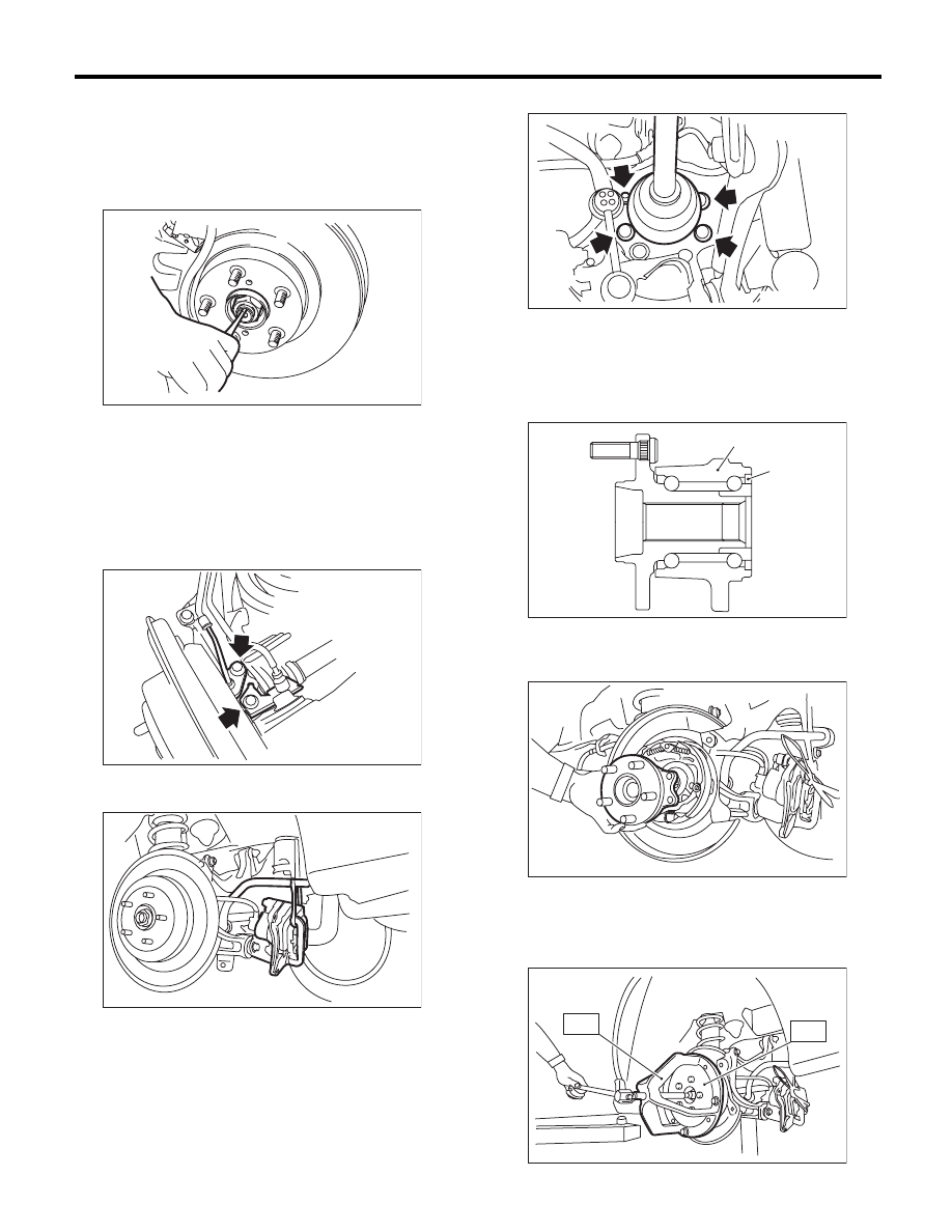
3) Lift the crimped section of axle nut.
4) While applying the parking brake, remove the
axle nut using a socket wrench.
CAUTION:
Remove the wheel before loosening the axle
nut. Failure to follow this rule may damage the
wheel bearings.
5) Release the parking brake.
6) Remove the rear ABS wheel speed sensor.
7) Remove the disc brake caliper from back plate,
and suspend it from the stabilizer using a wire.
8) Remove the disc rotor from the hub.
NOTE:
• Mark the mating surface of hub and disc rotor be-
fore removing the disc rotor to avoid confusing
when installing.
• If it is difficult to remove the disc rotor from the
hub, drive the 8 mm bolt into the threaded end of ro-
tor, and then remove the rotor.
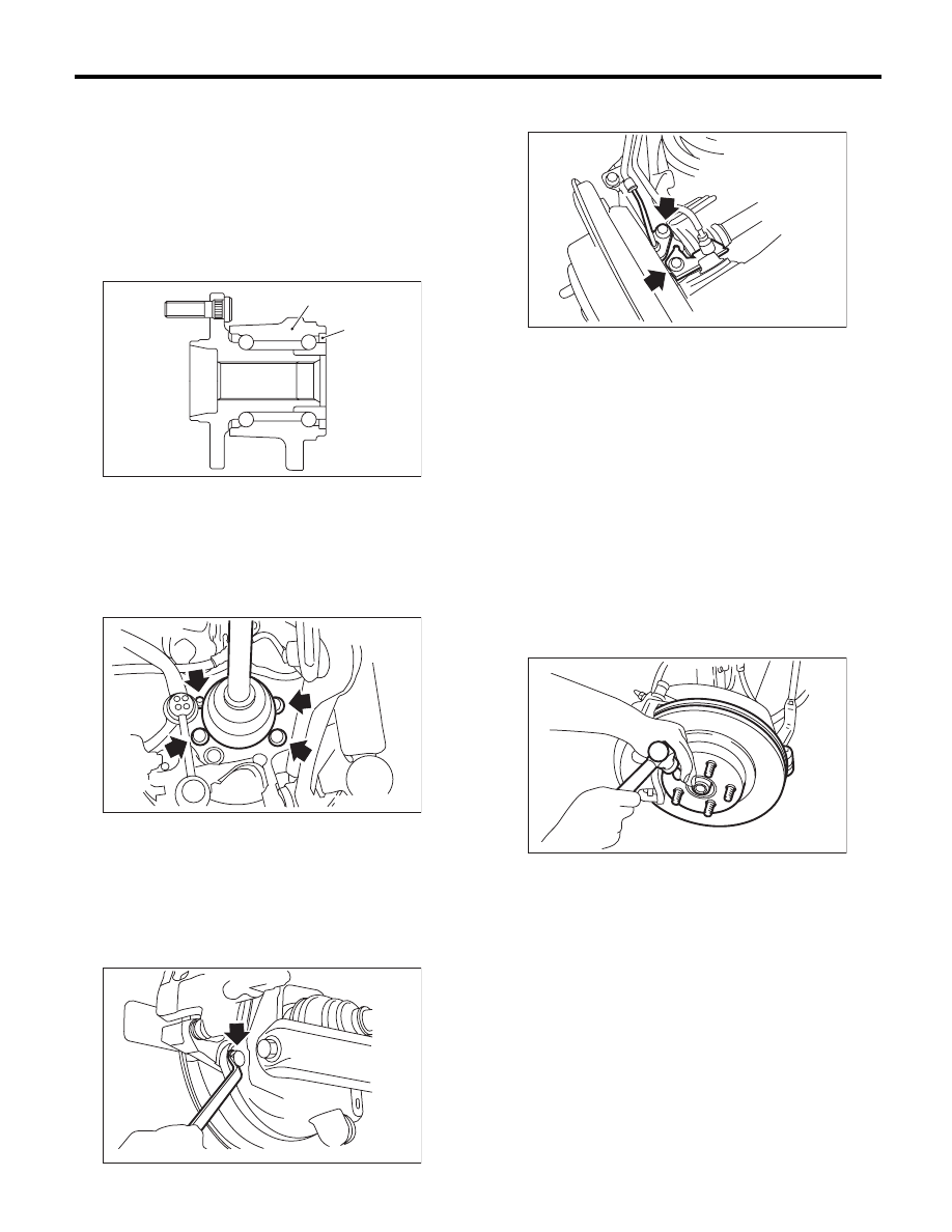
9) Remove the four bolts from rear arm.
10) Remove the hub unit bearing.
CAUTION:
• Be careful not to damage the magnetic encoder.
• Do not get closer the tool which charged
magnetism to magnetic encoder.
NOTE:
If it is hard to remove, use the ST.
ST1
926470000
AXLE SHAFT PULLER
ST2
28099PA110 AXLE SHAFT PULLER PLATE
DS-00038
DS-00147
DS-00148
(1) Magnetic encoder
(2) Rear hub unit bearing
DS-00149
DS-00251
(2)
(1)
DS-00150
DS-00122
ST2
ST1
DS-20
Rear Hub Unit Bearing
DRIVE SHAFT SYSTEM
B: INSTALLATION
1) Aligning the hub unit bearing to the mounting
hole of the back plate, install the hub unit assembly
and back plate. Tighten the axle nut temporarily.
CAUTION:
• Be careful not to damage the magnetic en-
coder.
• Do not get closer the tool which charged
magnetism to magnetic encoder.
2) Tighten the four bolts.
Tightening torque:
65 N·m (6.6 kgf-m, 47.9 ft-lb)
3) Remove the axle nut.
4) Draw the rear drive shaft into specified position.
5) Tighten the new axle nut temporarily.
6) Install the disc rotor to hub.
7) Install the disc brake caliper on the back plate.
Tightening torque:
66 N·m (6.7 kgf-m, 48.7 ft-lb)
8) Install the rear ABS wheel speed sensor and
brake cable bracket.
9) Adjust the parking brake lever stroke by turning
the adjuster. <Ref. to PB-4, ADJUSTMENT, Park-
ing Brake Lever.>
10) While applying the parking brake and depress-
ing the brake pedal, tighten a new axle nut to the
specified torque and lock it securely.
Tightening torque:
240 N·m (24.5 kgf-m, 177 ft-lb)
CAUTION:
• Install the wheel after installation of axle nut.
Failure to follow this rule may damage the
wheel bearing.
• Be sure to tighten the axle nut to specified
torque. Do not overtighten it as this may dam-
age the wheel bearing.
11) After tightening the axle nut, lock it securely.
12) Install the wheel and tighten the wheel nuts to
specified torque.
Tightening torque:
120 N·m (12.2 kgf-m, 88.5 ft-lb)
(1) Magnetic encoder
(2) Rear hub unit bearing
DS-00251
(2)
(1)
DS-00149
DS-00152
DS-00147
DS-00048
Нет комментариевНе стесняйтесь поделиться с нами вашим ценным мнением.
Текст