Subaru Legacy IV (2008 year). Service manual — part 1186
LAN(diag)-78
Diagnostic Procedure with Diagnostic Trouble Code (DTC)
LAN SYSTEM (DIAGNOSTICS)
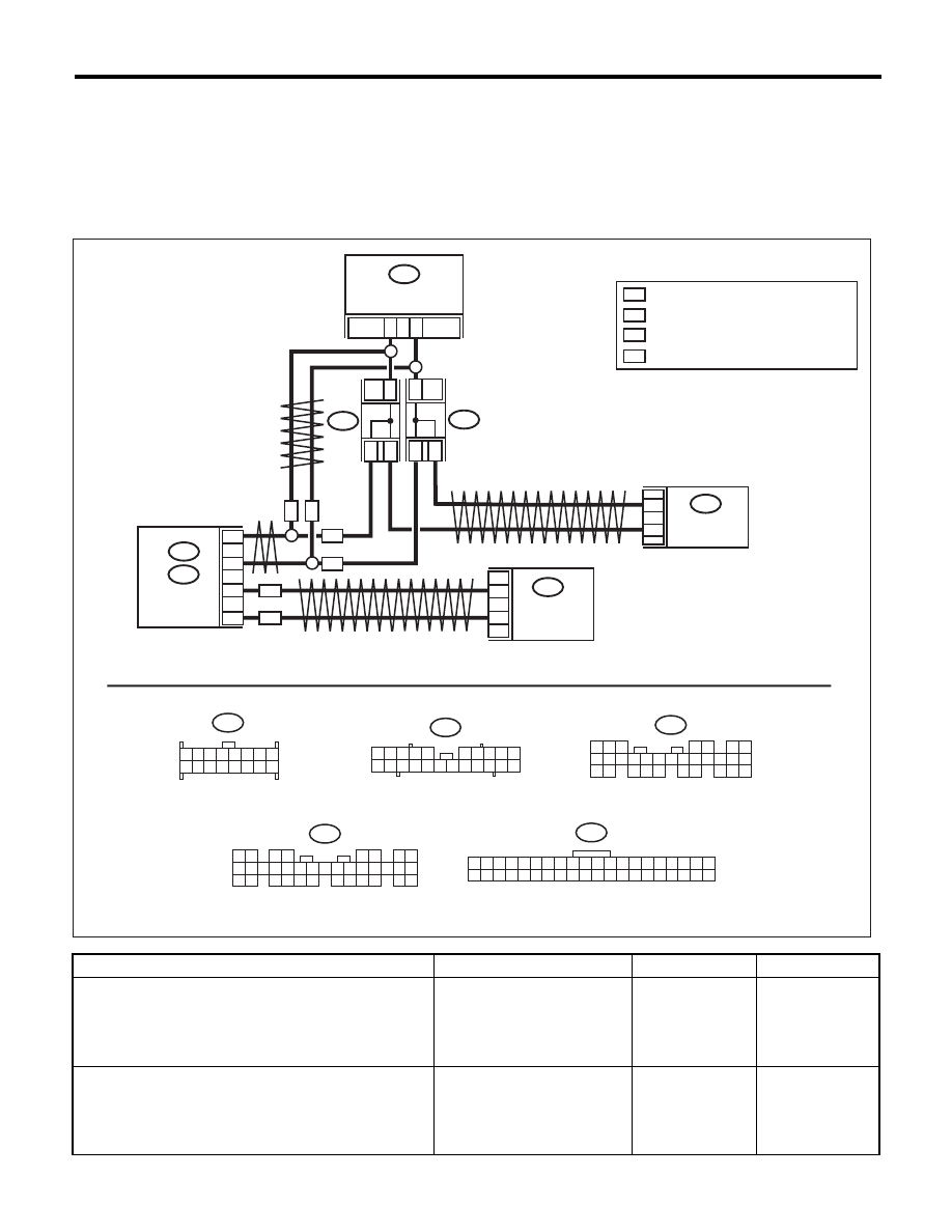
T: DTC U1313 CAN-LS MONITOR DATA ABNORMAL
DTC DETECTING CONDITION:
Center display unit error, or harness between the main harness splice and center display unit is open or
shorted, the connector is not connected securely and the terminal has poor crimping.
TROUBLE SYMPTOM:
“Er LC” is displayed in odo/trip meter. (Except for meter with MID)
WIRING DIAGRAM:
Step
Check
Yes
No
1
CHECK CENTER MONITOR.
1) Display the current data of body integrated
unit using Subaru Select Monitor.
2) Display the “center display failure”.
Is OK displayed?
Go to step 2.
Refer to the navi-
gation display.
<Ref. to ET-19,
REMOVAL, Navi-
gation Display.>
2
CHECK NAVIGATION.
1) Display the current data of body integrated
unit using Subaru Select Monitor.
2) Display NAVI failure.
Is OK displayed?
Refer to the navi-
gation display.
<Ref. to ET-19,
REMOVAL, Navi-
gation Display.>
Refer to navigation
body. <Ref. to ET-
21, REMOVAL,
Navigation Body.>
i106
i10
B282
21
22
14
6
i119
A27
A26
B26
B25
i84
B280
10
9
B:
A:
B:
i107
*
1
*
1
*
1
*
1
*
1
*
1
i10
LAN00383
CAN
JOINT
CONNECTOR
ON
WN
WN
ON
TWISTED PAIR LINE
TWISTED PAIR LINE
COMBINATION METER
BODY
INTEGRATED
UNIT
i119
1 2 3 4 5 6 7 8
9 10 11 12 13 14 15 16
1 2 3 4 5
6 7 8 9 10
11 12
19 20 21
13 14 15 16 17 18
22
5
4
6 7
8
2
1
9
3
10
22
23
11 12 13 14 15
24 25
26 27
16 17 18
28 29
19 20
21
30
B280
A:
i84
1 2
3 4
5 6
7 8
9 10 11 12
14 15 16 17 18 19 20 21 22 23
24 25
26 27 28 29
30 31 32 33
34 35
13
B282
1 2 3 4 5 6 7 8 9 10 11 12 13 14 15 16 17 18 19 20
21 22 23 24 25 26 27 28 29 30 31 32 33 34 35 36 37 38 39 40
*
1
ON
WN
WA
WA
WA
AUTO A/C
CONTROL
MODULE
CENTER
DISPLAY
: TERMINAL No. OPTIONAL ARRANGEMENT
: WITH NAVIGATION
: WITHOUT NAVIGATION
: WITH AUTO A/C
LAN(diag)-79
Diagnostic Procedure with Diagnostic Trouble Code (DTC)
LAN SYSTEM (DIAGNOSTICS)
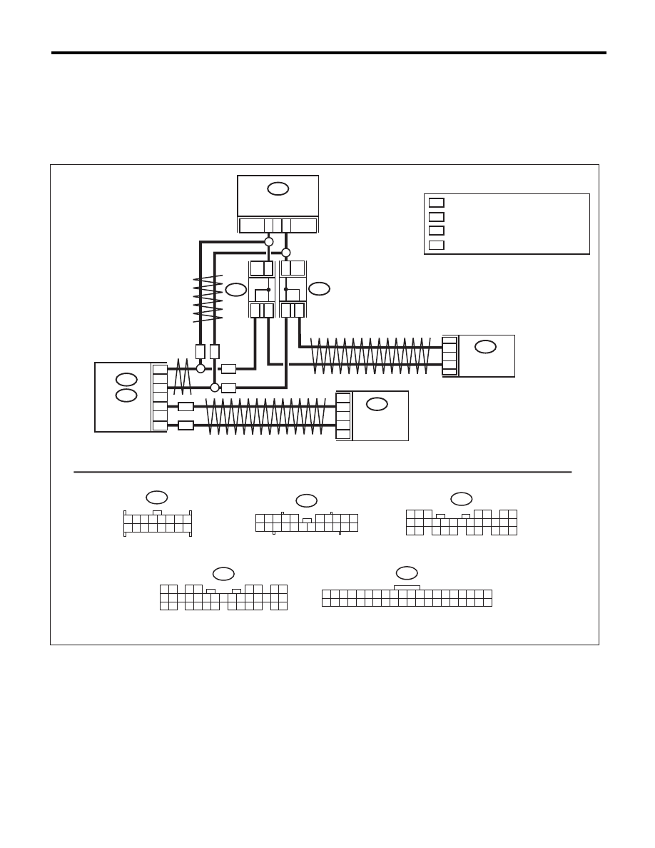
U: DTC U1321 CAN-LS METER NO-RECEIVE DATA
DTC DETECTING CONDITION:
Combination meter unit error, or harness between the main harness splice and combination meter unit is
open or shorted, the connector is not connected properly and the terminal has poor crimping.
TROUBLE SYMPTOM:
Fail mode occurs because the data is not received from combination meter unit.
WIRING DIAGRAM:
i106
i10
B282
21
22
14
6
i119
A27
A26
B26
B25
i84
B280
10
9
B:
A:
B:
i107
*
1
*
1
*
1
*
1
*
1
*
1
i10
LAN00383
CAN
JOINT
CONNECTOR
ON
WN
WN
ON
TWISTED PAIR LINE
TWISTED PAIR LINE
COMBINATION METER
BODY
INTEGRATED
UNIT
i119
1 2 3 4 5 6 7 8
9 10 11 12 13 14 15 16
1 2 3 4 5
6 7 8 9 10
11 12
19 20 21
13 14 15 16 17 18
22
5
4
6 7
8
2
1
9
3
10
22
23
11 12 13 14 15
24 25
26 27
16 17 18
28 29
19 20
21
30
B280
A:
i84
1 2
3 4
5 6
7 8
9 10 11 12
14 15 16 17 18 19 20 21 22 23
24 25
26 27 28 29
30 31 32 33
34 35
13
B282
1 2 3 4 5 6 7 8 9 10 11 12 13 14 15 16 17 18 19 20
21 22 23 24 25 26 27 28 29 30 31 32 33 34 35 36 37 38 39 40
*
1
ON
WN
WA
WA
WA
AUTO A/C
CONTROL
MODULE
CENTER
DISPLAY
: TERMINAL No. OPTIONAL ARRANGEMENT
: WITH NAVIGATION
: WITHOUT NAVIGATION
: WITH AUTO A/C

LAN(diag)-80
Diagnostic Procedure with Diagnostic Trouble Code (DTC)
LAN SYSTEM (DIAGNOSTICS)
Step
Check
Yes
No
1
CHECK COMMUNICATION LINE.
1) Warm up the engine.
2) Compare the data of body integrated unit
and combination meter using Subaru Select
Monitor.
Check item:
• Engine speed
• Shift range
Is the data displayed same?
Go to step 2.
Perform the self-
diagnosis of com-
bination meter.
<Ref. to IDI-5,
SELF-DIAGNO-
SIS, INSPEC-
TION,
Combination Meter
System.>
2
CHECK HARNESS.
1) Disconnect the body integrated unit and
combination meter connector.
2) Measure the resistance between harness
connectors.
Connector & terminal
(i10) No. 21 — (i84) No. 27:
(i10) No. 22 — (i84) No. 26:
Is the resistance less than 10
:? Go to step 4.
Go to step 3.
3
CHECK HARNESS.
Measure the resistance between harness con-
nector and chassis ground with the connector of
the unit disconnected.
Connector & terminal
(i10) No. 21 — Chassis ground:
(i10) No. 22 — Chassis ground:
Is the resistance less than 10
:? Go to step 4.
Repair or replace
the open circuit of
harness.
4
CHECK COMBINATION METER.
Perform the self-diagnosis of combination
meter. <Ref. to IDI-5, SELF-DIAGNOSIS,
INSPECTION, Combination Meter System.>
Is the self-diagnosis OK?
Temporary poor
contact occurs.
Check the connec-
tion of each con-
nector.
Replace the com-
bination meter.
<Ref. to IDI-22,
REMOVAL, Com-
bination Meter.>
LAN(diag)-81
Diagnostic Procedure with Diagnostic Trouble Code (DTC)
LAN SYSTEM (DIAGNOSTICS)
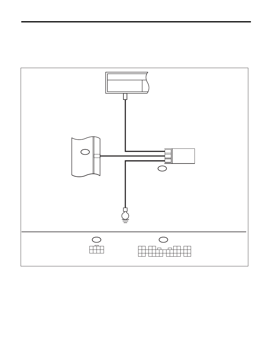
V: DTC B1500 KEYLESS UART COM. MALFUNCTION
DTC DETECTING CONDITION:
UART between keyless control unit and body integrated unit is open or shorted, the connector is not con-
nected properly, or the terminal is crimped improperly.
TROUBLE SYMPTOM:
Door lock does not operate with keyless.
WIRING DIAGRAM:
FB-10
M/B FUSE
NO.8 (B)
4
3
7
9
A4
i84
i96
E
i84
i96
1 2 3 4
5 6 7 8
LAN00268
1 2
3 4
5 6
7 8
9 10 11 12
14 15 16 17 18 19 20 21 22 23
24 25
26 27 28 29
30 31 32 33
34 35
13
TO POWER SUPPLY CIRCUIT
KEYLESS ENTRY CONTROL MODULE
BODY
INTEGRATED
UNIT
Нет комментариевНе стесняйтесь поделиться с нами вашим ценным мнением.
Текст