Subaru Legacy IV (2008 year). Service manual — part 822
6MT-101
Front Differential Assembly
MANUAL TRANSMISSION AND DIFFERENTIAL
B: INSTALLATION
1) Install the differential assembly to the clutch
housing.
2) Apply oil to the screw threads of the side retain-
er.
3) Remove the O-rings on both sides of the side re-
tainer.
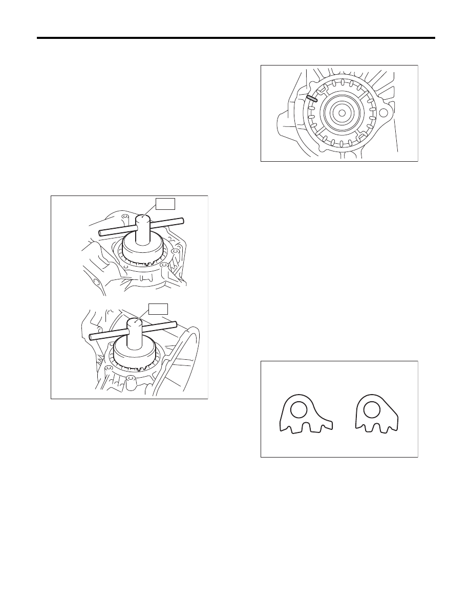
4) Install the differential side retainers to both
sides, using the ST.
ST1
18630AA010
WRENCH COMPL
RETAINER (RH SIDE)
ST2
18630AA000
WRENCH ASSEMBLY
(LH SIDE)
NOTE:
Be careful not to damage the oil seal.
5) Inspect and adjust the hypoid gear backlash.
<Ref. to 6MT-107, HYPOID GEAR BACKLASH,
INSPECTION, Front Differential Assembly.>
6) Inspect and adjust the tooth contact. <Ref. to
6MT-98, ADJUSTMENT, Drive Pinion Shaft As-
sembly.>
7) Mark the mating positions of the left and right
side retainers and the clutch housing.
8) Remove the differential side retainers from both
sides.
NOTE:
When removing the side retainer, record how many
times it was turned to remove.
9) Install new O-rings to the side retainers on both
sides.
10) Attach the differential side retainers to both
sides.
NOTE:
When attaching, turn the side retainer the same
number of turns it took to remove, and align the
marks.
11) Install the lock plate.
Tightening torque:
25 N·m (2.5 kgf-m, 18.4 ft-lb)
NOTE:
Be careful not to confuse the left and right side lock
plates.
12) Remove any remaining liquid gasket from the
clutch housing and adapter plate.
(A) LH side
(B) RH side
(A)
(B)
MT-00657
ST1
ST2
(A) LH
(B) RH
MT-00658
MT-00659
(A)
(B)
6MT-102
Front Differential Assembly
MANUAL TRANSMISSION AND DIFFERENTIAL
13) Apply liquid gasket to the clutch housing.
Liquid gasket:
THREE BOND 1215 (Part No. 004403007) or
equivalent
14) Install the drive pinion shaft assembly. <Ref. to
6MT-94, INSTALLATION, Drive Pinion Shaft As-
sembly.>
15) Install the individual gear assemblies all at
once. <Ref. to 6MT-65, INSTALLATION, Main
Shaft Assembly.>
16) Install the transmission case. <Ref. to 6MT-60,
INSTALLATION, Transmission Case.>
17) Install the center differential. <Ref. to 6MT-57,
INSTALLATION, Center Differential.>
18) Install the transfer driven gear. <Ref. to 6MT-
55, INSTALLATION, Transfer Driven Gear.>
19) Install the extension case. <Ref. to 6MT-43, IN-
STALLATION, Extension Case.>
20) Install the neutral position switch, back-up light
switch and harness. <Ref. to 6MT-41, INSTALLA-
TION, Neutral Position Switch.> <Ref. to 6MT-39,
INSTALLATION, Back-up Light Switch.>
21) Install the manual transmission assembly to the
vehicle. <Ref. to 6MT-34, INSTALLATION, Manual
Transmission Assembly.>
C: DISASSEMBLY
1. DIFFERENTIAL CASE
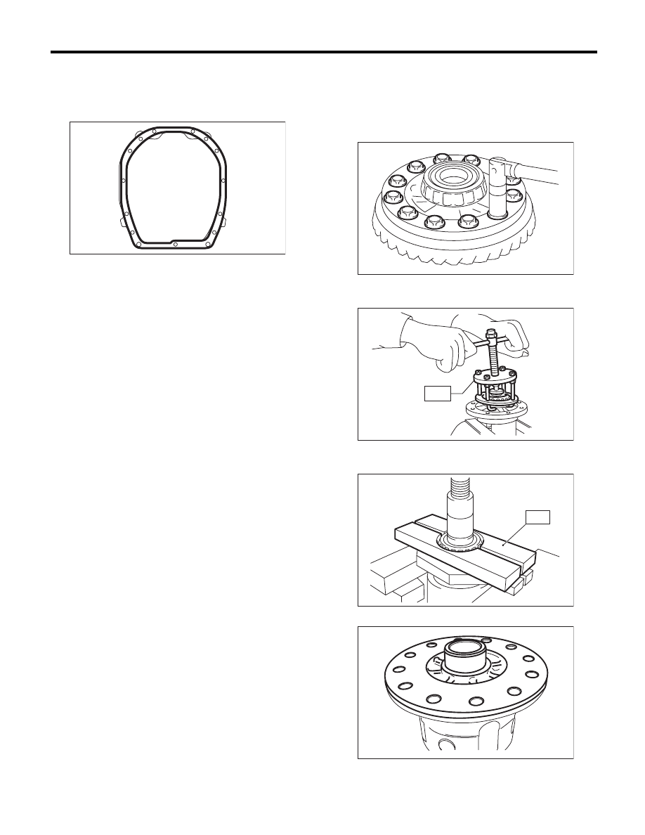
1) Fix the differential assembly on a vise, and re-
move the hypoid driven gear.
ST
18270KA020
SOCKET (E20)
2) Using the ST, remove the roller bearing.
ST
399527700
PULLER SET
3) Using the ST, remove the roller bearing.
ST
498077000
REMOVER
4) Remove the differential case LH.
MT-00532
MT-00660
MT-00663
ST
MT-00665
ST
MT-01532
6MT-103
Front Differential Assembly
MANUAL TRANSMISSION AND DIFFERENTIAL
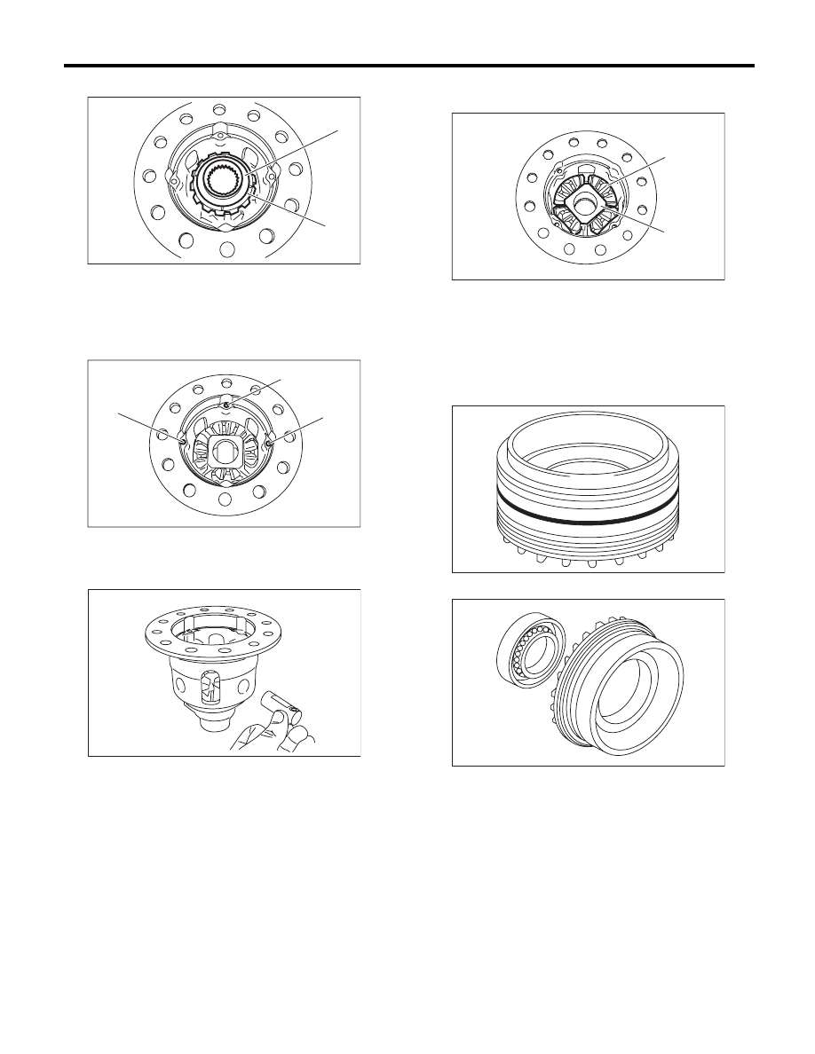
5) Remove the differential bevel gear and washer.
6) Using a magnet tool, etc., remove 3 straight
pins.
7) Remove 3 pinion shafts.
8) Remove differential bevel pinion and pinion shaft
joint.
9) Remove the differential bevel gear and washer.
2. SIDE RETAINER
1) Remove the O-ring.
2) Remove the oil seal.
(A) Differential bevel gear
(B) Washer
(A) Straight pin
MT-01533
(B)
(A)
MT-01534
(A)
(A)
(A)
MT-01535
(A) Differential bevel pinion
(B) Pinion shaft joint
MT-01536
(A)
(B)
MT-00666
AT-00220
6MT-104
Front Differential Assembly
MANUAL TRANSMISSION AND DIFFERENTIAL
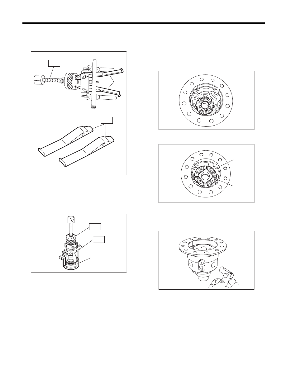
3) Remove the claw of ST1, and attach the claw of
ST2.
ST1
398527700
PULLER ASSY
ST2
18760AA000
CLAW
4) Remove the bearing outer race from the side re-
tainer, using the ST.
ST1
398527700
PULLER ASSY
ST2
18760AA000
CLAW
D: ASSEMBLY
1. DIFFERENTIAL CASE
1) Install differential bevel gear and washer to the
differential case RH.
NOTE:
Face the chamfered side of washer toward gear.
2) Install differential bevel pinion and pinion shaft
joint.
3) Install 3 pinion shafts.
(A) CLAW
(A) Side retainer
MT-00668
(A)
ST2
ST1
MT-00669
(A)
ST2
ST1
(A) Differential bevel pinion
(B) Pinion shaft joint
MT-01537
MT-01536
(A)
(B)
MT-01535
Нет комментариевНе стесняйтесь поделиться с нами вашим ценным мнением.
Текст