Subaru Legacy IV (2008 year). Service manual — part 823
6MT-105
Front Differential Assembly
MANUAL TRANSMISSION AND DIFFERENTIAL
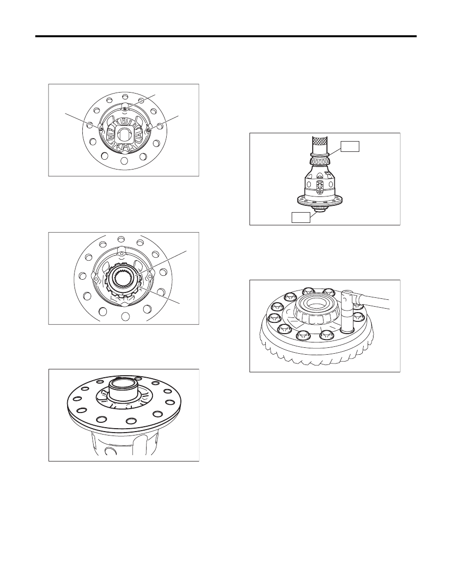
4) Install 3 straight pins.
NOTE:
Make sure the straight pins are inserted complete-
ly.
5) Attach the differential bevel gear and washer.
NOTE:
Face the chamfered side of washer toward gear.
6) Install the differential case LH.
7) Use the ST to attach bearings of differential cas-
es RH and LH.
ST1
398437700
INSTALLER
ST2
398497701
SEAT
CAUTION:
Do not apply pressure in excess of 20 kN (2.0
ton, 2.2 US ton, 2.0 Imp ton).
NOTE:
Always replace bearings and outer races as a set.
8) Attach the hypoid driven gear to the differential
case.
ST
18270KA020
SOCKET (E20)
Tightening torque:
69 N·m (7.0 kgf-m, 50.9 ft-lb)
9) Inspect the backlash of the bevel pinion gear.
<Ref. to 6MT-106, BEVEL PINION GEAR BACK-
LASH, INSPECTION, Front Differential Assem-
bly.>
(A) Straight pin
(A) Differential bevel gear
(B) Washer
MT-01534
(A)
(A)
(A)
MT-01533
(B)
(A)
MT-01532
MT-01538
ST1
ST2
MT-00660
6MT-106
Front Differential Assembly
MANUAL TRANSMISSION AND DIFFERENTIAL
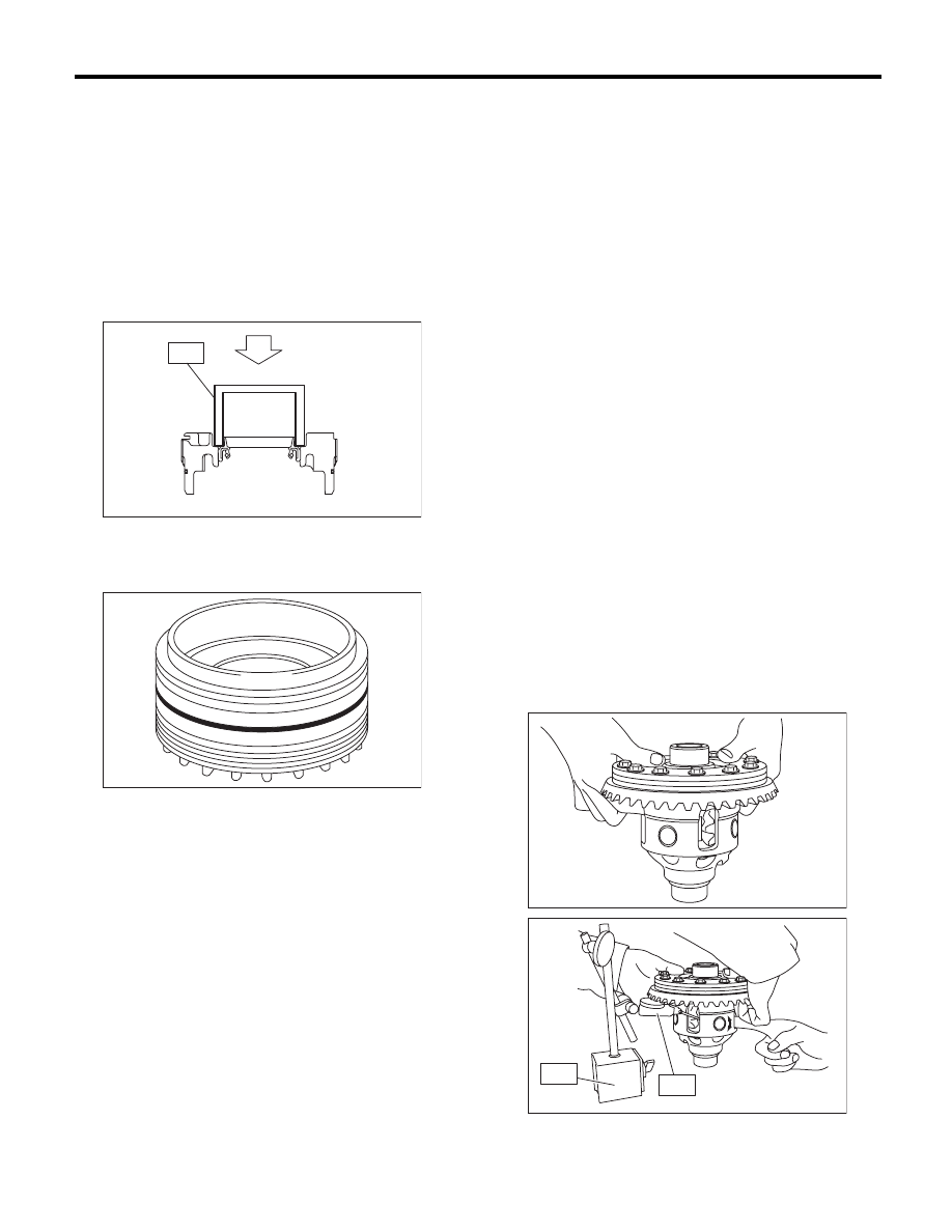
2. SIDE RETAINER
NOTE:
Install the oil seal and O-ring of side retainer after
the adjustment of backlash and tooth contact.
1) Install the bearing outer race to side retainer.
2) Using the ST, install the oil seal.
ST
18675AA000
DIFFERENTIAL SIDE OIL
SEAL INSTALLER
NOTE:
• Use a new oil seal.
• Apply oil to the oil seal lips.
3) Install the O-ring.
NOTE:
Use new O-rings.
E: INSPECTION
Repair or replace the differential in the following
cases:
• If gears are damaged, seized, or are excessively
worn.
• If differential case sliding surfaces are damaged,
seized, or are excessively worn.
• If there is damage, rust or wear in the bearings or
bearing locations.
• If the bearing does not rotate smoothly or an ab-
normal noise is emitted when turning.
1. BEVEL PINION GEAR BACKLASH
Measure the backlash of the differential bevel pin-
ion. If backlash is not within standard value, install
a suitable washer to adjust. <Ref. to 6MT-108, AD-
JUSTMENT, Front Differential Assembly.>
CAUTION:
When measuring the backlash, hold the differ-
ential assembly in upright position.
NOTE:
• It is recommended that backlash be measured
by 2 people. One person should push the differen-
tial bevel gear upward (differential case LH side),
and the other person measure the backlash.
• Before measuring backlash, turn so that the
gears will settle in their individual locations.
ST1
498247001
MAGNET BASE
ST2
498247100
DIAL GAUGE
Standard backlash
0.13 — 0.18 mm (0.0051 — 0.0071 in)
AT-00226
ST
AT-00219
MT-01542
MT-01543
ST1
ST2
6MT-107
Front Differential Assembly
MANUAL TRANSMISSION AND DIFFERENTIAL
2. HYPOID GEAR BACKLASH
Inspect the hypoid gear backlash. Adjust if out of
standard. <Ref. to 6MT-108, HYPOID GEAR
BACKLASH, ADJUSTMENT, Front Differential As-
sembly.>
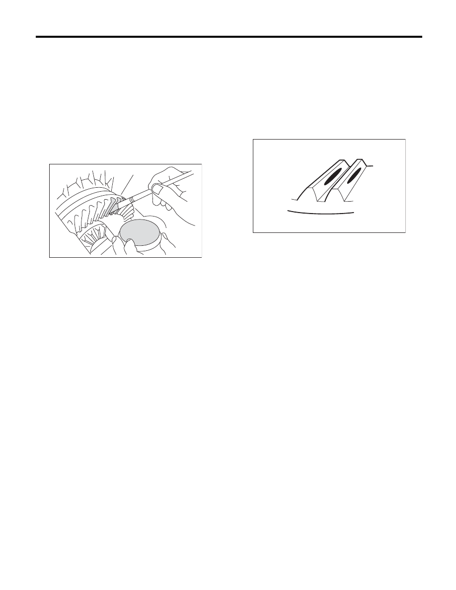
3. TOOTH CONTACT OF HYPOID GEAR
1) Check that the hypoid gear backlash is within the
standard value. Adjust if out of standard. <Ref. to
6MT-108, HYPOID GEAR BACKLASH, ADJUST-
MENT, Front Differential Assembly.>
2) Apply a thin uniform coat of lead-free red dye on
the surfaces of 3 or 4 hypoid driven gear teeth.
3) Attach the drive pinion shaft assembly, and affix
with 4 bolts.
NOTE:
Use old gaskets and washers to prevent the mating
surfaces of the housing from becoming damaged.
Tightening torque:
50 N·m (5.1 kgf-m, 36.9 ft-lb)
4) Turn the drive pinion shaft to the left and right for
several turns.
5) Remove the drive pinion shaft assembly, and in-
spect the mating condition of the teeth. If tooth con-
tact is not correct, perform adjustment. <Ref. to
6MT-98, ADJUSTMENT, Drive Pinion Shaft As-
sembly.>
• Correct tooth contact
NOTE:
In a no load condition, the tooth contact from the
center to the toe side is 50-60% (While driving, the
tooth contact will shift towards the heel side.).
MT-00652
(A) Toe side
(B) Heel side
(A)
(B)
MT-01401
6MT-108
Front Differential Assembly
MANUAL TRANSMISSION AND DIFFERENTIAL
F: ADJUSTMENT
1. BEVEL PINION GEAR BACKLASH
1) Measure the backlash of the bevel pinion gear.
<Ref. to 6MT-106, BEVEL PINION GEAR BACK-
LASH, INSPECTION, Front Differential Assem-
bly.>
2) Disassemble the differential case. <Ref. to 6MT-
102, DIFFERENTIAL CASE, DISASSEMBLY,
Front Differential Assembly.>
3) Select a washer from the following table, and as-
semble the differential case. <Ref. to 6MT-104,
DIFFERENTIAL CASE, ASSEMBLY, Front Differ-
ential Assembly.>
NOTE:
If the backlash is excessive, select a thicker wash-
er. If the backlash is too small, select a thinner
washer.
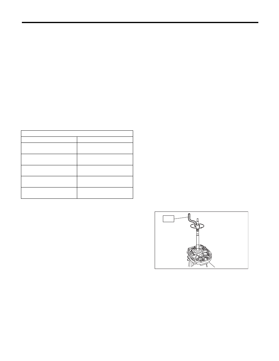
2. HYPOID GEAR BACKLASH
1) Attach the RH and LH side retainers.
ST1
18630AA010
WRENCH COMPL
RETAINER (RH SIDE)
ST2
18630AA000
WRENCH ASSEMBLY
(LH SIDE)
NOTE:
• Twist in the RH side side retainer a little further
than the LH side.
• WRENCH ASSEMBLY (499787000) can also be
used.
2) Attach the drive pinion shaft assembly, and affix
with 4 bolts.
NOTE:
Use old gaskets and washers to prevent the mating
surfaces of the housing from becoming damaged.
Tightening torque:
50 N·m (5.1 kgf-m, 36.9 ft-lb)
3) Using the ST, twist in the side retainer LH until it
just contacts the drive pinion and hypoid driven
gear. Loosen side retainer RH.
ST1
18630AA010
WRENCH COMPL
RETAINER (RH SIDE)
ST2
18630AA000
WRENCH ASSEMBLY
(LH SIDE)
NOTE:
WRENCH ASSEMBLY (499787000) can also be
used.
4) Use the ST to turn the drive pinion shaft a few
times.
ST
18631AA000
HANDLE
5) Repeat steps 3) and 4) until side retainer LH
does not turn anymore. For side retainer RH, twist
in until the inner race and outer race just comes into
contact. This is the “zero” backlash state.
Washer
Part No.
Thickness mm (in)
803038021
0.950
(0.0374)
803038022
1.000
(0.0394)
803038023
1.050
(0.0413)
803038024
0.900
(0.0354)
803038025
1.100
(0.0433)
MT-00653
ST
Нет комментариевНе стесняйтесь поделиться с нами вашим ценным мнением.
Текст