Subaru Legacy IV (2008 year). Service manual — part 568
EN(H6DO)(diag)-245
Diagnostic Procedure with Diagnostic Trouble Code (DTC)
ENGINE (DIAGNOSTICS)
CG:DTC P0451 EVAPORATIVE EMISSION CONTROL SYSTEM PRESSURE
SENSOR
DTC DETECTING CONDITION:
• Two consecutive driving cycles with fault
• GENERAL DESCRIPTION <Ref. to GD(H6DO)-128, DTC P0451 EVAPORATIVE EMISSION CONTROL
SYSTEM PRESSURE SENSOR, Diagnostic Trouble Code (DTC) Detecting Criteria.>
CAUTION:
After repair or replacement of faulty parts, perform Clear Memory Mode <Ref. to EN(H6DO)(diag)-52,
OPERATION, Clear Memory Mode.>, and Inspection Mode <Ref. to EN(H6DO)(diag)-44, PROCEDURE,
Inspection Mode.>.
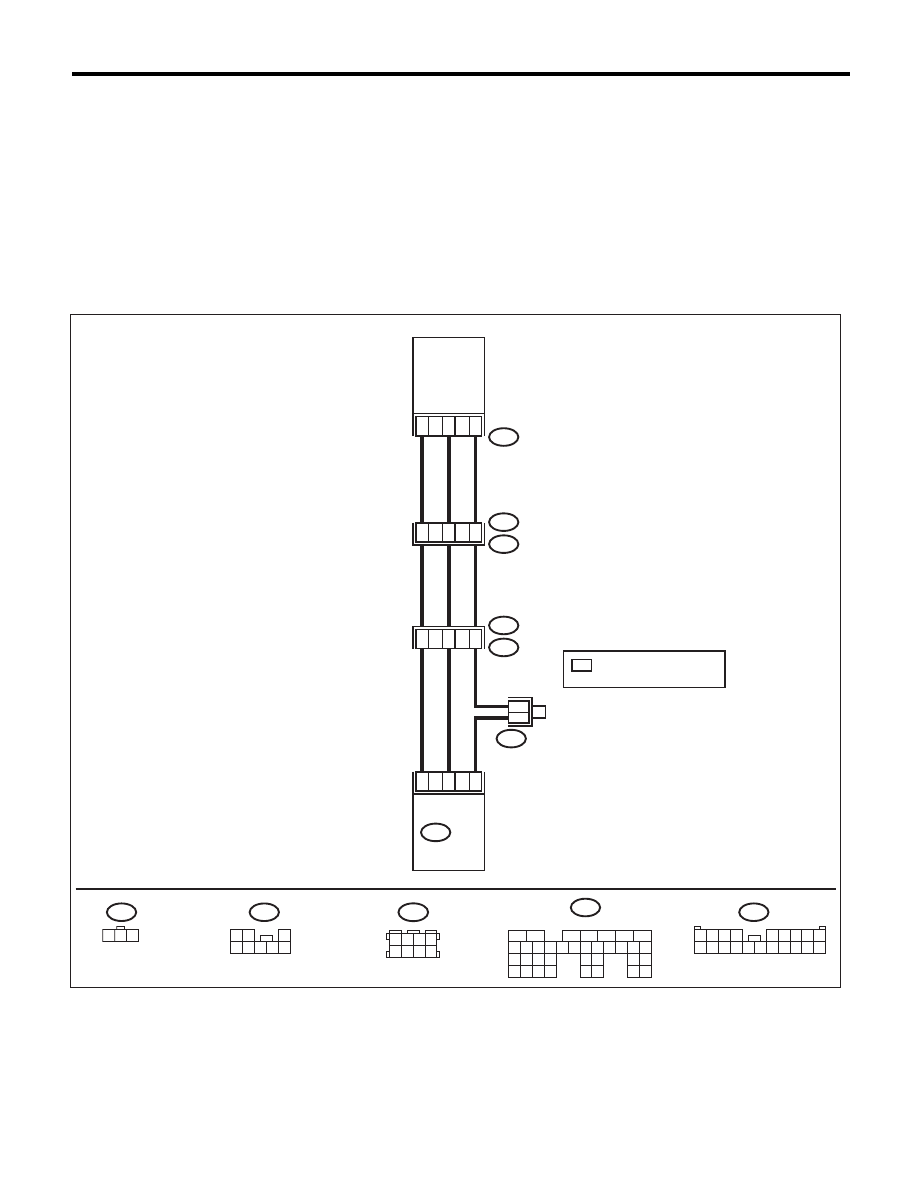
WIRING DIAGRAM:
B83
3
1
2
22
32
30
ECM
B135
R47
R213
R15
R1
B97
B97
1 2 3
R47
B135
7
4
6
6
13
17
B83
R213
FUEL
TANK
PRESSURE
SENSOR
1 2 3 4
5 6 7 8 9
10 11 12 13 14 15 16 17 18 19 20
3 4
5 6
1 2
7 8
1 2
3
4 5 6 7 8
:TERMINAL No. OPTIONAL
ARRANGEMENT
*
*
*
5
6
7
8
2
1
9
4
3
10
24
22 23
25
11 12 13 14 15
26 27
28
16 17 18 19
20 21
29 30 31
32 33
34 35
EN-05233
EN(H6DO)(diag)-246
Diagnostic Procedure with Diagnostic Trouble Code (DTC)
ENGINE (DIAGNOSTICS)
Step
Check
Yes
No
1
CHECK FUEL FILLER CAP.
1) Turn the ignition switch to OFF.
2) Open the fuel flap.
Is the fuel filler cap tightened
securely?
Go to step 2.
Tighten fuel filler
cap securely.
2
CHECK PRESSURE VACUUM LINE.
NOTE:
Check the following items.
• Disconnection, leakage and clogging of the
vacuum hoses and pipes between fuel tank
pressure sensor and fuel tank
• Disconnection, leakage and clogging of the
air ventilation hoses and pipes between fuel fill-
er pipe and fuel tank
Is there any fault in pressure/
vacuum line?
Repair or replace
the hoses and
pipes.
Replace the fuel
tank pressure sen-
sor. <Ref. to
EC(H6DO)-12,
Fuel Tank Pres-
sure Sensor.>

EN(H6DO)(diag)-247
Diagnostic Procedure with Diagnostic Trouble Code (DTC)
ENGINE (DIAGNOSTICS)
CH:DTC P0452 EVAPORATIVE EMISSION CONTROL SYSTEM PRESSURE
SENSOR LOW INPUT
DTC DETECTING CONDITION:
• Immediately at fault recognition
• GENERAL DESCRIPTION <Ref. to GD(H6DO)-130, DTC P0452 EVAPORATIVE EMISSION CONTROL
SYSTEM PRESSURE SENSOR LOW INPUT, Diagnostic Trouble Code (DTC) Detecting Criteria.>
CAUTION:
After repair or replacement of faulty parts, perform Clear Memory Mode <Ref. to EN(H6DO)(diag)-52,
OPERATION, Clear Memory Mode.>, and Inspection Mode <Ref. to EN(H6DO)(diag)-44, PROCEDURE,
Inspection Mode.>.
WIRING DIAGRAM:
B83
3
1
2
22
32
30
ECM
B135
R47
R213
R15
R1
B97
B97
1 2 3
R47
B135
7
4
6
6
13
17
B83
R213
FUEL
TANK
PRESSURE
SENSOR
1 2 3 4
5 6 7 8 9
10 11 12 13 14 15 16 17 18 19 20
3 4
5 6
1 2
7 8
1 2
3
4 5 6 7 8
:TERMINAL No. OPTIONAL
ARRANGEMENT
*
*
*
5
6
7
8
2
1
9
4
3
10
24
22 23
25
11 12 13 14 15
26 27
28
16 17 18 19
20 21
29 30 31
32 33
34 35
EN-05233

EN(H6DO)(diag)-248
Diagnostic Procedure with Diagnostic Trouble Code (DTC)
ENGINE (DIAGNOSTICS)
Step
Check
Yes
No
1
CHECK CURRENT DATA.
1) Turn the ignition switch to ON.
2) Read the data of fuel tank pressure sensor
signal using the Subaru Select Monitor or gen-
eral scan tool.
NOTE:
• SUBARU SELECT MONITOR
For detailed operation procedure, refer to
“READ CURRENT DATA FOR ENGINE”. <Ref.
to EN(H6DO)(diag)-34, Subaru Select Moni-
tor.>
• General Scan Tool
For detailed operation procedures, refer to the
general scan tool operation manual.
Is the measured value less than
–7.45 kPa (–55.85 mmHg,
–2.2003 inHg) ?
Go to step 2.
Even if DTC is
detected, the cir-
cuit has returned to
a normal condition
at this time. Repro-
duce the failure,
and then perform
the diagnosis
again.
NOTE:
In this case, tem-
porary poor con-
tact of connector
may be the cause.
2
CHECK FUEL TANK PRESSURE SENSOR
POWER SOURCE.
1) Turn the ignition switch to OFF.
2) Disconnect the connector from the fuel tank
pressure sensor.
3) Turn the ignition switch to ON.
4) Measure the voltage between the fuel tank
pressure sensor connector and chassis ground.
Connector & terminal
(R47) No. 3 (+) — Chassis ground (–):
Is the voltage 4.5 V or more?
Go to step 3.
Repair the harness
and connector.
NOTE:
In this case, repair
the following item:
• Open circuit of
harness between
ECM and fuel tank
pressure sensor
connector
• Poor contact in
ECM connector
• Poor contact of
coupling connector
3
CHECK HARNESS BETWEEN ECM AND
FUEL TANK PRESSURE SENSOR CONNEC-
TOR.
1) Turn the ignition switch to OFF.
2) Disconnect the connectors from ECM.
3) Measure the resistance of harness between
the ECM and fuel tank pressure sensor connec-
tor.
Connector & terminal
(B135) No. 32 — (R47) No. 2:
Is the resistance less than 1
:? Go to step 4.
Repair the harness
and connector.
NOTE:
In this case, repair
the following item:
• Open circuit of
harness between
ECM and fuel tank
pressure sensor
connector
• Poor contact of
coupling connector
4
CHECK HARNESS BETWEEN ECM AND
FUEL TANK PRESSURE SENSOR CONNEC-
TOR.
Measure the resistance between ECM and
chassis ground.
Connector & terminal
(B135) No. 32 — Chassis ground:
Is the resistance 1 M
: or
more?
Go to step 5.
Repair the ground
short circuit of har-
ness between
ECM and fuel tank
pressure sensor
connector.
5
CHECK POOR CONTACT.
Check for poor contact between the ECM and
fuel tank pressure sensor connector.
Is there poor contact in the
ECM or fuel tank pressure sen-
sor connector?
Repair the poor
contact in the ECM
or fuel tank pres-
sure sensor con-
nector.
Replace the fuel
tank pressure sen-
sor. <Ref. to
EC(H6DO)-12,
Fuel Tank Pres-
sure Sensor.>
Нет комментариевНе стесняйтесь поделиться с нами вашим ценным мнением.
Текст