Subaru Legacy IV (2008 year). Service manual — part 567
EN(H6DO)(diag)-241
Diagnostic Procedure with Diagnostic Trouble Code (DTC)
ENGINE (DIAGNOSTICS)
CE:DTC P0447 EVAPORATIVE EMISSION CONTROL SYSTEM VENT CONTROL
CIRCUIT OPEN
DTC DETECTING CONDITION:
• Immediately at fault recognition
• GENERAL DESCRIPTION <Ref. to GD(H6DO)-124, DTC P0447 EVAPORATIVE EMISSION CONTROL
SYSTEM VENT CONTROL CIRCUIT OPEN, Diagnostic Trouble Code (DTC) Detecting Criteria.>
CAUTION:
After repair or replacement of faulty parts, perform Clear Memory Mode <Ref. to EN(H6DO)(diag)-52,
OPERATION, Clear Memory Mode.>, and Inspection Mode <Ref. to EN(H6DO)(diag)-44, PROCEDURE,
Inspection Mode.>.
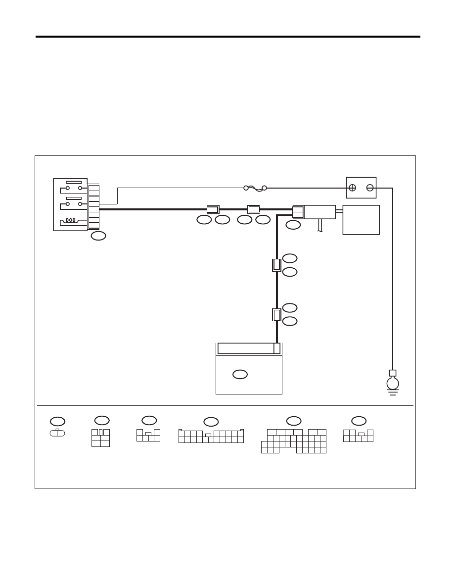
WIRING DIAGRAM:
16
10 11 12 13 14 15
25
24
30
9
8
7
17 18 19 20
28
21 22 23
29
32
31
1
2
3
4
5
6
27
26
33 34 35
SBF-7
R144
R67
R213
R46
R15
R1
R1
B97
B97
B47
ECM
E
17
1
2
5
3
6
4
2
1
6
1
14
B136
CANISTER
DRAIN
VALVE
MAIN RELAY
BATTERY
7
R144
R67
B97
B47
3
4
1
2
5
6
B136
R213
1
2
3 4 5 6
1 2 3 4
5 6 7 8 9
10 11 12 13 14 15 16 17 18 19 20
1 2
1 2
3
4 5 6 7 8
EN-05232

EN(H6DO)(diag)-242
Diagnostic Procedure with Diagnostic Trouble Code (DTC)
ENGINE (DIAGNOSTICS)
Step
Check
Yes
No
1
CHECK OUTPUT SIGNAL OF ECM.
1) Turn the ignition switch to ON.
2) Measure the voltage between ECM and
chassis ground.
Connector & terminal
(B136) No. 17 (+) — Chassis ground (–):
Is the voltage 10 V or more?
Check for poor
contact of the ECM
connector.
Go to step 2.
2
CHECK HARNESS BETWEEN ECM AND
DRAIN VALVE.
1) Turn the ignition switch to OFF.
2) Disconnect the connectors from the ECM
and drain valve.
3) Measure the resistance between the drain
valve connector and chassis ground.
Connector & terminal
(R144) No. 2 — Chassis ground:
Is the resistance 1 M
: or
more?
Go to step 3.
Repair the ground
short circuit of har-
ness between
ECM and drain
valve connector.
3
CHECK HARNESS BETWEEN ECM AND
DRAIN VALVE.
Measure the resistance of harness between
ECM and drain valve connector.
Connector & terminal
(B136) No. 17 — (R144) No. 2:
Is the resistance less than 1
:? Go to step 4.
Repair the harness
and connector.
NOTE:
In this case, repair
the following item:
• Open circuit in
harness between
ECM and drain
valve connector
• Poor contact of
coupling connector
4
CHECK DRAIN VALVE.
Measure the resistance between drain valve
terminals.
Terminals
No. 1 — No. 2:
Is the resistance between 10 —
100
:?
Go to step 5.
Replace the drain
valve. <Ref. to
EC(H6DO)-16,
Drain Valve.>
5
CHECK POWER SUPPLY TO DRAIN VALVE.
1) Turn the ignition switch to ON.
2) Measure the voltage between drain valve
and chassis ground.
Connector & terminal
(R144) No. 1 (+) — Chassis ground (–):
Is the voltage 10 V or more?
Repair poor con-
tact of the drain
valve connector.
Repair the harness
and connector.
NOTE:
In this case, repair
the following item:
• Open circuit of
harness between
main relay and
drain valve
• Poor contact of
coupling connector
• Poor contact of
main relay connec-
tor

EN(H6DO)(diag)-243
Diagnostic Procedure with Diagnostic Trouble Code (DTC)
ENGINE (DIAGNOSTICS)
CF:DTC P0448 EVAPORATIVE EMISSION CONTROL SYSTEM VENT CONTROL
CIRCUIT SHORTED
DTC DETECTING CONDITION:
• Immediately at fault recognition
• GENERAL DESCRIPTION <Ref. to GD(H6DO)-126, DTC P0448 EVAPORATIVE EMISSION CONTROL
SYSTEM VENT CONTROL CIRCUIT SHORTED, Diagnostic Trouble Code (DTC) Detecting Criteria.>
CAUTION:
After repair or replacement of faulty parts, perform Clear Memory Mode <Ref. to EN(H6DO)(diag)-52,
OPERATION, Clear Memory Mode.>, and Inspection Mode <Ref. to EN(H6DO)(diag)-44, PROCEDURE,
Inspection Mode.>.
WIRING DIAGRAM:
16
10 11 12 13 14 15
25
24
30
9
8
7
17 18 19 20
28
21 22 23
29
32
31
1
2
3
4
5
6
27
26
33 34 35
SBF-7
R144
R67
R213
R46
R15
R1
R1
B97
B97
B47
ECM
E
17
1
2
5
3
6
4
2
1
6
1
14
B136
CANISTER
DRAIN
VALVE
MAIN RELAY
BATTERY
7
R144
R67
B97
B47
3
4
1
2
5
6
B136
R213
1
2
3 4 5 6
1 2 3 4
5 6 7 8 9
10 11 12 13 14 15 16 17 18 19 20
1 2
1 2
3
4 5 6 7 8
EN-05232

EN(H6DO)(diag)-244
Diagnostic Procedure with Diagnostic Trouble Code (DTC)
ENGINE (DIAGNOSTICS)
Step
Check
Yes
No
1
CHECK HARNESS BETWEEN ECM AND
DRAIN VALVE.
1) Turn the ignition switch to OFF.
2) Disconnect the connectors from the ECM
and drain valve.
3) Turn the ignition switch to ON.
4) Measure the voltage between ECM and
chassis ground.
Connector & terminal
(B136) No. 17 (+) — Chassis ground (–):
Is the voltage 10 V or more?
Repair the short
circuit to the power
supply in the har-
ness between the
ECM and drain
valve connector.
Go to step 2.
2
CHECK DRAIN VALVE.
1) Turn the ignition switch to OFF.
2) Measure the resistance between drain valve
terminals.
Terminals
No. 1 — No. 2:
Is the resistance less than 1
:? Replace the drain
valve. <Ref. to
EC(H6DO)-16,
Drain Valve.>
Repair the poor
contact of ECM
connector.
Нет комментариевНе стесняйтесь поделиться с нами вашим ценным мнением.
Текст