Subaru Legacy IV (2008 year). Service manual — part 793
5MT-68
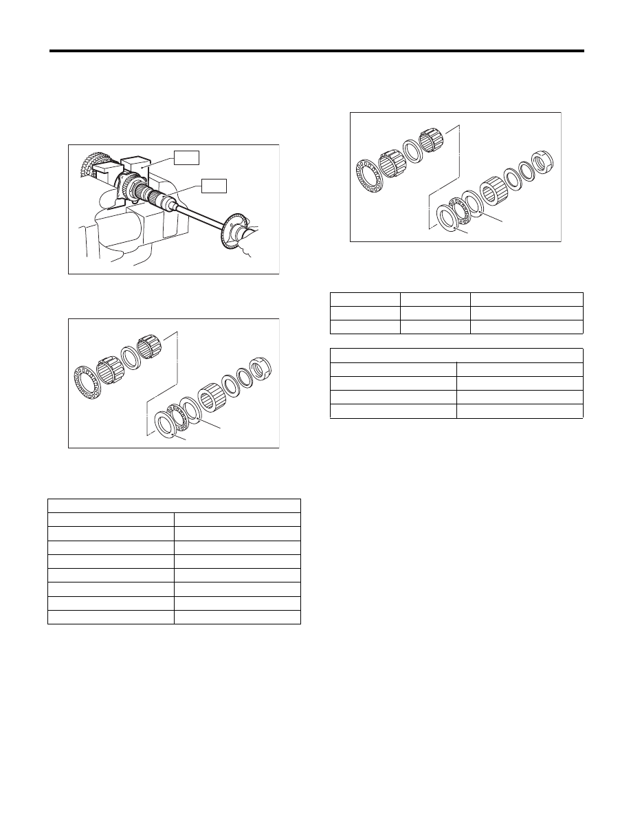
Drive Pinion Shaft Assembly
MANUAL TRANSMISSION AND DIFFERENTIAL
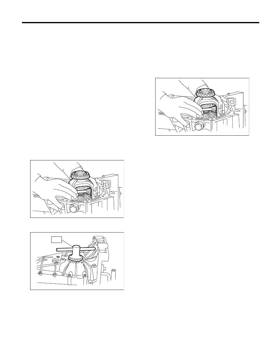
3) After removing the ST2, measure the starting
torque using torque driver.
ST1
899884100
HOLDER
ST3
899988608
SOCKET WRENCH (27)
Starting torque:
0.3 — 0.8 N·m (0.03 — 0.08 kgf-m, 0.2 — 0.6 ft-lb)
4) If the starting torque is not within the specified
limit, select new adjusting washer No. 1 and re-
check starting torque.
5) If the specified starting torque cannot be ob-
tained by the selection of washer No. 1, select ad-
justing washer No. 2 from the list below. Repeat
steps 1) through 4) to adjust starting torque.
6) Recheck that the starting torque is within the
specified range, then crimp the lock nut at four po-
sitions.
(A) Adjusting washer No. 1
(B) Adjusting washer No. 2
Adjusting washer No. 1
Part number
Thickness mm (in)
803025051
3.925 (0.1545)
803025052
3.950 (0.1555)
803025053
3.975 (0.1565)
803025054
4.000 (0.1575)
803025055
4.025 (0.1585)
803025056
4.050 (0.1594)
803025057
4.075 (0.1604)
MT-00269
ST1
ST3
MT-00270
( A )
( B )
(A) Adjusting washer No. 1
(B) Adjusting washer No. 2
Starting torque
Dimension H
Adjusting washer No. 2
Low
Small
Select thicker one.
High
Large
Select thinner one.
Adjusting washer No. 2
Part number
Thickness mm (in)
803025059
3.850 (0.1516)
803025054
4.000 (0.1575)
803025058
4.150 (0.1634)
MT-00270
( A )
( B )
5MT-69
Front Differential Assembly
MANUAL TRANSMISSION AND DIFFERENTIAL
17.Front Differential Assembly
A: REMOVAL
1) Remove the manual transmission assembly
from the vehicle. <Ref. to 5MT-24, REMOVAL,
Manual Transmission Assembly.>
2) Remove the transfer case together with the ex-
tension case assembly. <Ref. to 5MT-38, REMOV-
AL, Transfer Case and Extension Case
Assembly.>
3) Remove the transmission case. <Ref. to 5MT-
51, REMOVAL, Transmission Case.>
4) Remove the drive pinion shaft assembly. <Ref.
to 5MT-60, REMOVAL, Drive Pinion Shaft Assem-
bly.>
5) Remove the main shaft assembly for single-
range. <Ref. to 5MT-54, REMOVAL, Main Shaft
Assembly for Single-Range.>
6) Remove the front differential assembly.
NOTE:
• Do not confuse the right and left roller bearing
outer races.
• Be careful not to damage the oil seal of retainer.
7) Remove the differential side retainers using ST.
ST
18630AA010
WRENCH COMPL RETAINER
8) Remove the bearing outer race from the trans-
mission case.
ST
398527700
PULLER ASSY
B: INSTALLATION
1) Install the differential side retainers using ST.
ST
18630AA010
WRENCH COMPL RETAINER
2) Install the bearing outer race to the transmission
case.
3) Install the front differential assembly.
NOTE:
Be careful not to fold the sealing lip of oil seal.
4) Install the main shaft assembly for single-range.
<Ref. to 5MT-54, INSTALLATION, Main Shaft As-
sembly for Single-Range.>
5) Install the drive pinion shaft assembly. <Ref. to
5MT-60, INSTALLATION, Drive Pinion Shaft As-
sembly.>
6) Install the transmission case. <Ref. to 5MT-52,
INSTALLATION, Transmission Case.>
7) Install the transfer case together with the exten-
sion case assembly. <Ref. to 5MT-38, INSTALLA-
TION, Transfer Case and Extension Case
Assembly.>
8) Install the manual transmission assembly to the
vehicle. <Ref. to 5MT-27, INSTALLATION, Manual
Transmission Assembly.>
MT-00162
MT-00176
ST
MT-00162
5MT-70
Front Differential Assembly
MANUAL TRANSMISSION AND DIFFERENTIAL
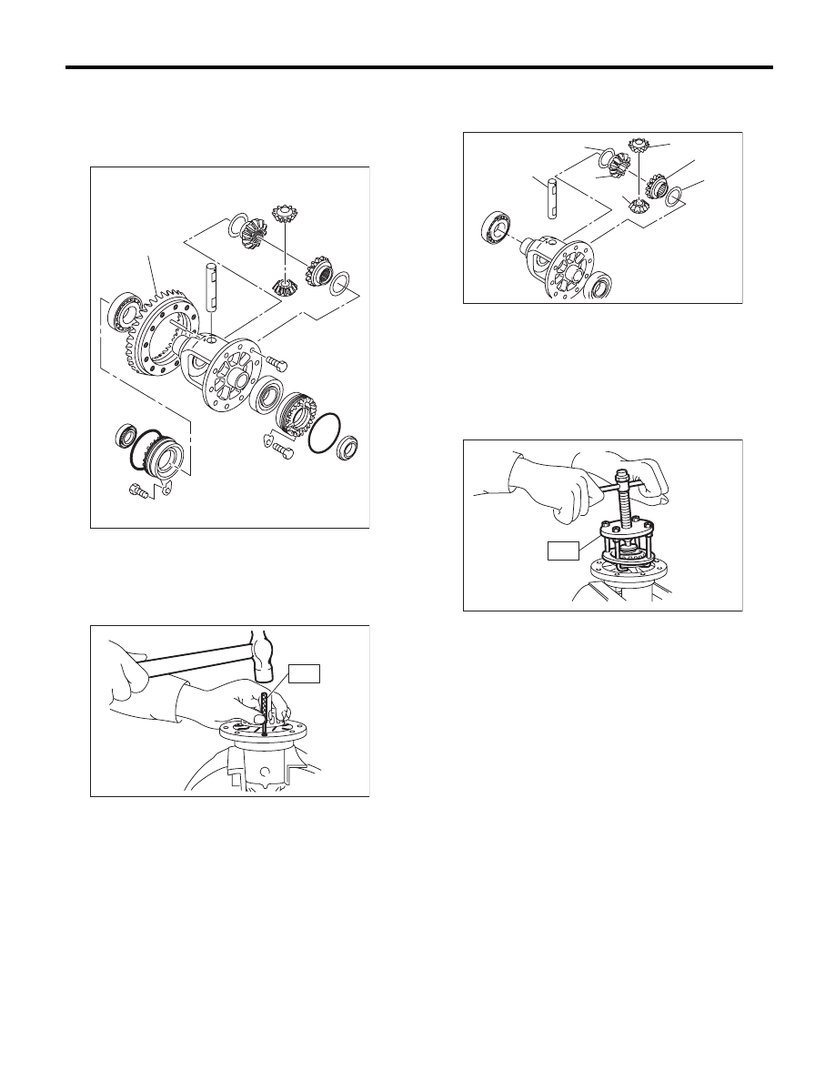
C: DISASSEMBLY
1. DIFFERENTIAL CASE ASSEMBLY
1) Loosen the twelve bolts and remove hypoid driv-
en gear.
2) Drive out the straight pin from differential assem-
bly toward hypoid driven gear side.
ST
899904100
REMOVER
3) Pull out the pinion shaft, and remove the differ-
ential bevel pinion, differential bevel gear and
washer.
4) Using the ST, remove the roller bearing.
ST
899524100
PULLER SET
(A) Hypoid driven gear
(A)
MT-00275
MT-00276
ST
(A) Pinion shaft
(B) Differential bevel pinion
(C) Differential bevel gear
(D) Washer
MT-00277
(A)
(D)
(D)
(C)
(C)
(B)
(B)
MT-00278
ST
5MT-71
Front Differential Assembly
MANUAL TRANSMISSION AND DIFFERENTIAL
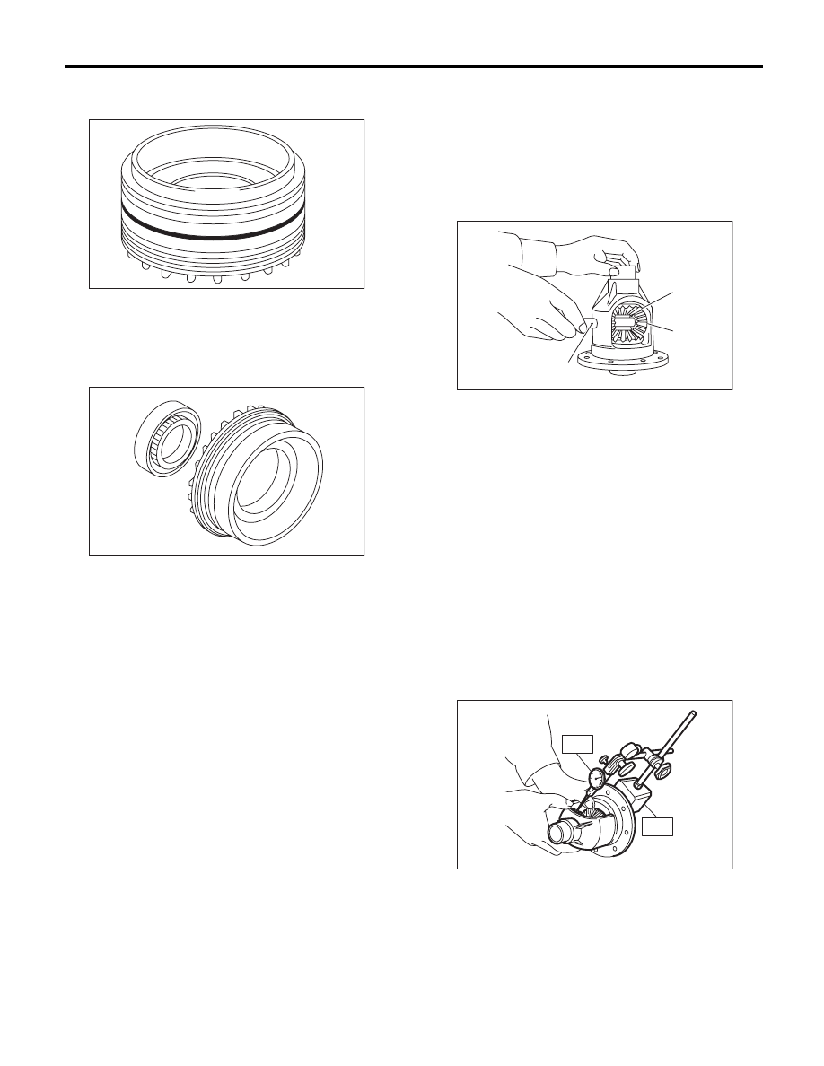
2. SIDE RETAINER
1) Remove the O-ring.
2) Remove the oil seal.
NOTE:
• Remove it by using flat tip screwdriver.
• Do not reuse the oil seal. Replace the oil seal
with a new part.
D: ASSEMBLY
1. DIFFERENTIAL CASE ASSEMBLY
1) Install the differential bevel gear and differential
bevel pinion together with washer, and insert the
pinion shaft.
NOTE:
Face the chamfered side of washer toward gear.
2) Measure the backlash between the differential
bevel gear and differential bevel pinion. If backlash
is not within specified value, install a suitable wash-
er to adjust. <Ref. to 5MT-73, BEVEL PINION
GEAR BACKLASH, INSPECTION, Front Differen-
tial Assembly.>
NOTE:
Be sure the pinion gear teeth contacts adjacent
gear teeth during measurement.
ST1
498247001
MAGNET BASE
ST2
498247100
DIAL GAUGE
Standard backlash
0.13 — 0.18 mm (0.0051 — 0.0071 in)
MT-00279
MT-01445
(A) Differential bevel pinion
(B) Differential bevel gear
(C) Pinion shaft
MT-00284
(A)
(B)
(C)
MT-00285
ST1
ST2
Нет комментариевНе стесняйтесь поделиться с нами вашим ценным мнением.
Текст