Subaru Legacy IV (2008 year). Service manual — part 791
5MT-60
Drive Pinion Shaft Assembly
MANUAL TRANSMISSION AND DIFFERENTIAL
16.Drive Pinion Shaft Assembly
A: REMOVAL
1) Remove the manual transmission assembly
from the vehicle. <Ref. to 5MT-24, REMOVAL,
Manual Transmission Assembly.>
2) Remove the transfer case together with the ex-
tension case assembly. <Ref. to 5MT-38, REMOV-
AL, Transfer Case and Extension Case
Assembly.>
3) Remove the transmission case. <Ref. to 5MT-
51, REMOVAL, Transmission Case.>
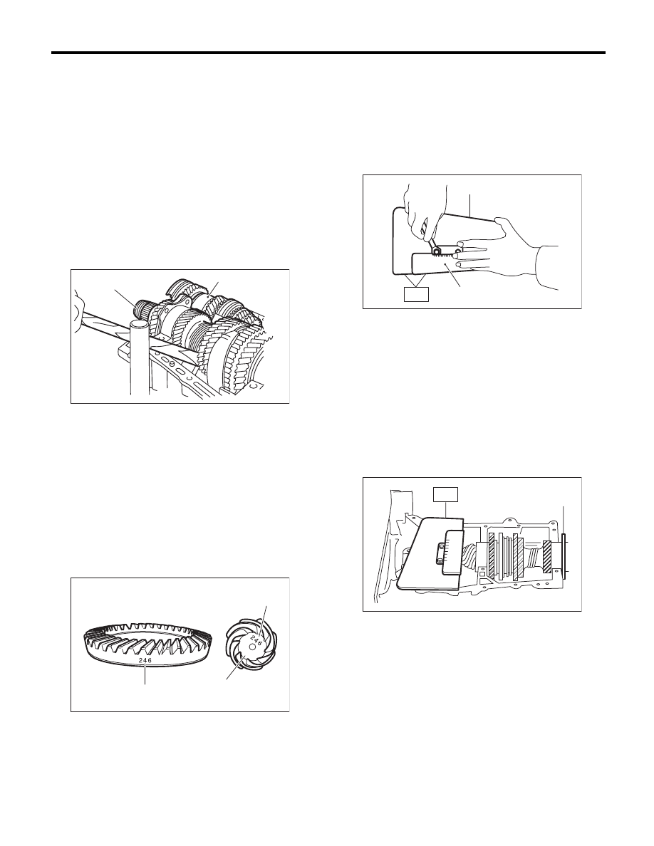
4) Remove the drive pinion shaft assembly.
NOTE:
Use a hammer handle, etc. to remove if too tight.
B: INSTALLATION
1) Remove the front differential assembly.
2) Alignment marks/numbers on hypoid gear set:
The number (A) on top of the drive pinion, and the
number on the hypoid driven gear are set numbers
for the two gears. Use a pair having the same num-
bers.
The figure (B) below shows a number for shim ad-
justment. If no number is shown, the value is zero.
3) Place the drive pinion shaft assembly on trans-
mission main case RH without shim and tighten the
bearing mounting bolts.
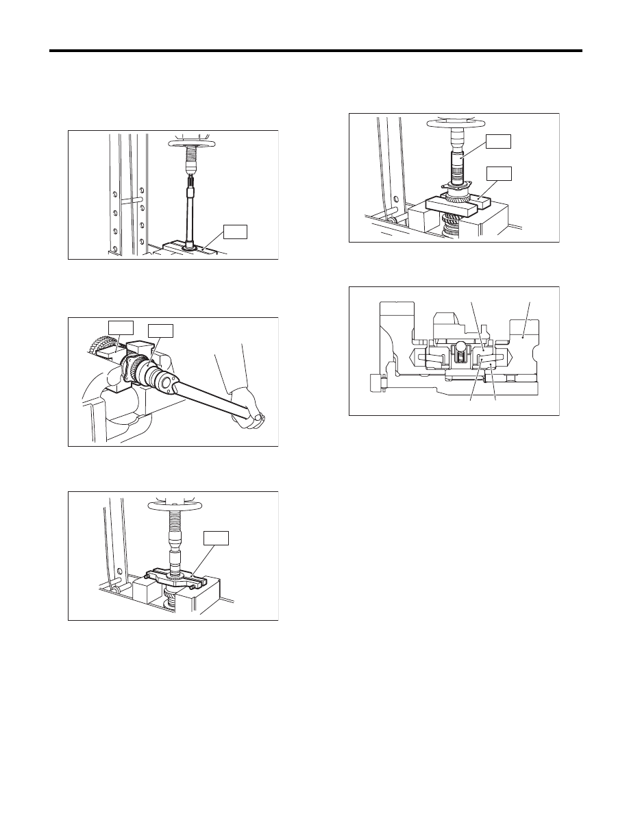
4) Check and adjust the ST.
NOTE:
• Loosen the two bolts and adjust so that the scale
indicates 0.5 correctly when the plate end and the
scale end are on the same level.
• Tighten the two bolts.
ST
499917500
DRIVE PINION GAUGE
ASSY
5) Position the ST by inserting the knock pin of ST
into the knock hole of transmission case.
ST
499917500
DRIVE PINION GAUGE
ASSY
6) Slide the drive pinion gauge scale with finger tip
and read the value at the point where it matches
with the end face of drive pinion.
ST
499917500
DRIVE PINION GAUGE
ASSY
7) The thickness of shim shall be determined by
adding the value indicated on drive pinion to the
value indicated on the ST. (Add if the number on
drive pinion is prefixed by +, and subtract if the
number is prefixed by –.)
ST
499917500
DRIVE PINION GAUGE
ASSY
(A) Main shaft ASSY for single range
(B) Drive pinion shaft ASSY
(A) Set number
(B) Number for shim adjustment
MT-00161
( A )
( B )
MT-00990
(A)
(B)
(A)
+0.1
(A) Plate
(B) Scale
(A) Adjust the clearance to zero without shim.
MT-00242
(A)
(B)
ST
MT-00243
(A)
ST
5MT-61
Drive Pinion Shaft Assembly
MANUAL TRANSMISSION AND DIFFERENTIAL
8) Select one to three shims in the following table
for the value determined as described above, and
take the shim(s) which thickness is closest to the
said value.
9) Install the front differential assembly. <Ref. to
5MT-69, INSTALLATION, Front Differential As-
sembly.>
10) Set the transmission main shaft assembly for
single range and drive pinion shaft assembly in the
install location. (When doing so, there will be no
clearance between the two when moved all the way
to the front). Inspect a suitable 1st-2nd, 3rd-4th and
5th shifter fork so that the coupling sleeve and re-
verse driven gear are positioned in the center of the
synchronizing mechanism. <Ref. to 5MT-66, IN-
SPECTION, Drive Pinion Shaft Assembly.>
11) Install the transmission case. <Ref. to 5MT-52,
INSTALLATION, Transmission Case.>
12) Install the transfer case together with the exten-
sion case assembly. <Ref. to 5MT-38, INSTALLA-
TION, Transfer Case and Extension Case
Assembly.>
13) Install the manual transmission assembly to the
vehicle. <Ref. to 5MT-27, INSTALLATION, Manual
Transmission Assembly.>
C: DISASSEMBLY
NOTE:
Attach a cloth to the end of driven shaft (on the fric-
tional side of the thrust needle bearing) to prevent
damage during disassembly or reassembly.
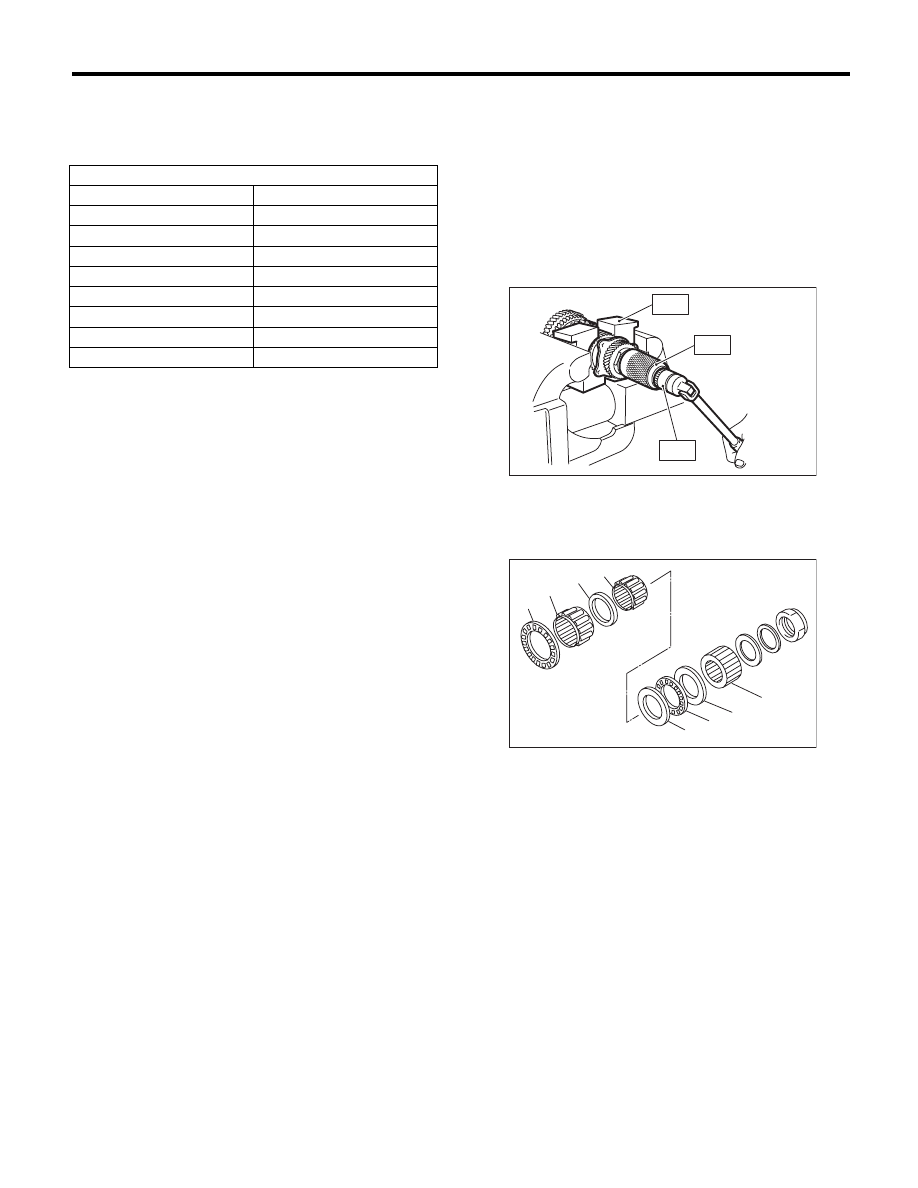
1) Flatten the tab of the lock nut. Remove the lock
nut with ST1, ST2 and ST3.
ST1
899884100
HOLDER
ST2
498427100
STOPPER
ST3
899988608
SOCKET WRENCH (27)
2) Draw out the drive pinion from driven shaft.
Remove the differential bevel gear sleeve, adjust-
ing washer No. 1, adjusting washer No. 2, thrust
bearing, needle bearing and drive pinion collar.
Drive pinion shim
Part number
Thickness mm (in)
32295AA031
0.150 (0.0059)
32295AA041
0.175 (0.0069)
32295AA051
0.200 (0.0079)
32295AA061
0.225 (0.0089)
32295AA071
0.250 (0.0098)
32295AA081
0.275 (0.0108)
32295AA091
0.300 (0.0118)
32295AA101
0.500 (0.0197)
(A) Differential bevel gear sleeve
(B) Adjusting washer No. 1 (25 × 37.5 × t)
(C) Thrust bearing (25 × 37.5 × 3)
(D) Adjusting washer No. 2 (25 × 37.5 × 4)
(E) Needle bearing (25 × 30 × 20)
(F) Drive pinion collar
(G) Needle bearing (30 × 37 × 23)
(H) Thrust bearing (33 × 50 × 3)
MT-00244
ST1
ST2
ST3
MT-00245
( B )
( D )
( C )
( A )
( F )
( H )
( G )
( E )
5MT-62
Drive Pinion Shaft Assembly
MANUAL TRANSMISSION AND DIFFERENTIAL
3) Remove the roller bearing and washer using ST
and a press.
NOTE:
Do not reuse the roller bearing.
ST
498077000
REMOVER
4) Flatten the tab of the lock nut. Remove the lock
nut using ST1 and ST2.
ST1
499987300
SOCKET WRENCH (50)
ST2
899884100
HOLDER
5) Remove the 5th driven gear using ST.
ST
499857000
5TH DRIVEN GEAR
REMOVER
6) Remove the woodruff key.
7) Remove the roller bearing and 3rd-4th driven
gear using ST1 and ST2.
ST1
499757002
INSTALLER
ST2
899714110
REMOVER
8) Remove the key.
9) Remove the 2nd driven gear, inner baulk ring,
synchro cone and outer baulk ring.
MT-00246
ST
MT-00247
ST1
ST2
MT-00248
S T
(A) 2nd driven gear
(B) Inner baulk ring
(C) Synchro cone
(D) Outer baulk ring
MT-00249
ST1
ST2
(A)
(B)
(C)
(D)
MT-01633
5MT-63
Drive Pinion Shaft Assembly
MANUAL TRANSMISSION AND DIFFERENTIAL
10) Remove the 1st driven gear, inner baulk ring,
synchro cone, outer baulk ring, 2nd gear bushing,
gear and hub using ST1 and ST2.
NOTE:
If necessary, use a new gear & hub assembly as a
set, when replacing the gear or hub. Because these
must engage at the specified point, avoid disas-
sembly as much as possible. If it must be disas-
sembled, mark the engaging point on the spline
beforehand.
ST1
499757002
INSTALLER
ST2
899714110
REMOVER
11) Remove the sub gear, washer and snap ring
(outer) of the 1st driven gear. (Non-turbo model)
D: ASSEMBLY
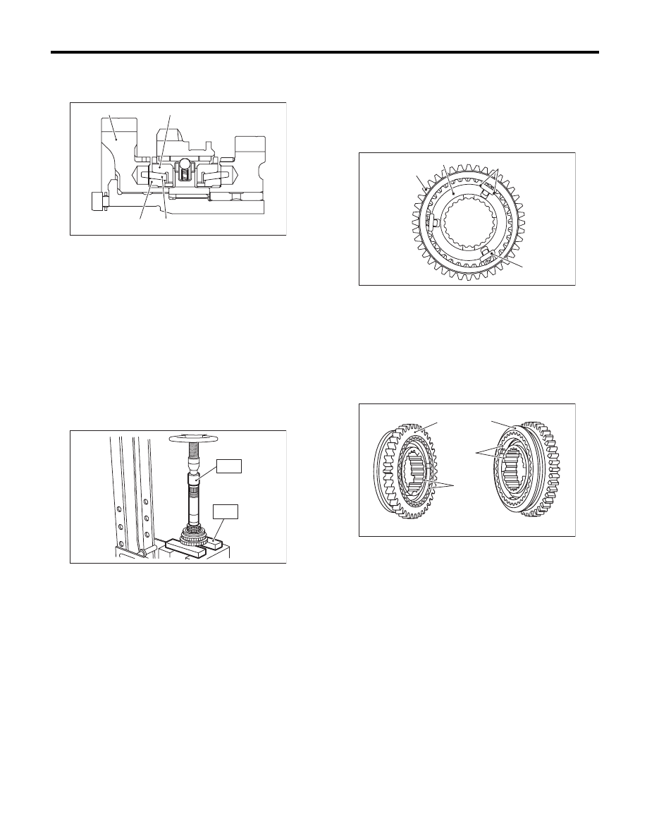
1) Install the sleeve and gear & hub assembly by
matching alignment marks.
NOTE:
After installation, make sure there is no significant
gap at both sides of the ball detent.
NOTE:
Use the new gear & hub assembly, if replacing the
gear or hub.
2) Install the washer, snap ring (outer) and sub
gear onto the 1st driven gear. (Non-turbo model)
(A) 1st driven gear
(B) Inner baulk ring
(C) Synchro cone
(D) Outer baulk ring
(D)
(C)
(B)
(A)
MT-01634
MT-00251
ST1
ST2
(A) Ball detent
(B) 1st-2nd synchronizer hub
(C) Reverse driven gear
(D) There is no large clearance at this part.
(A) 1st gear side
(B) 2nd gear side
(C) Flush surface
(D) Stepped surface
MT-01639
(A)
(D)
(B)
(C)
MT-00252
( B )
( A )
( C )
( D )
Нет комментариевНе стесняйтесь поделиться с нами вашим ценным мнением.
Текст