Subaru Legacy IV (2008 year). Service manual — part 514
EN(H6DO)(diag)-29
General Scan Tool
ENGINE (DIAGNOSTICS)
8. General Scan Tool
A: OPERATION
1. HOW TO USE GENERAL SCAN TOOL
1) Prepare a scan tool (general scan tool) required
by SAE J1978.
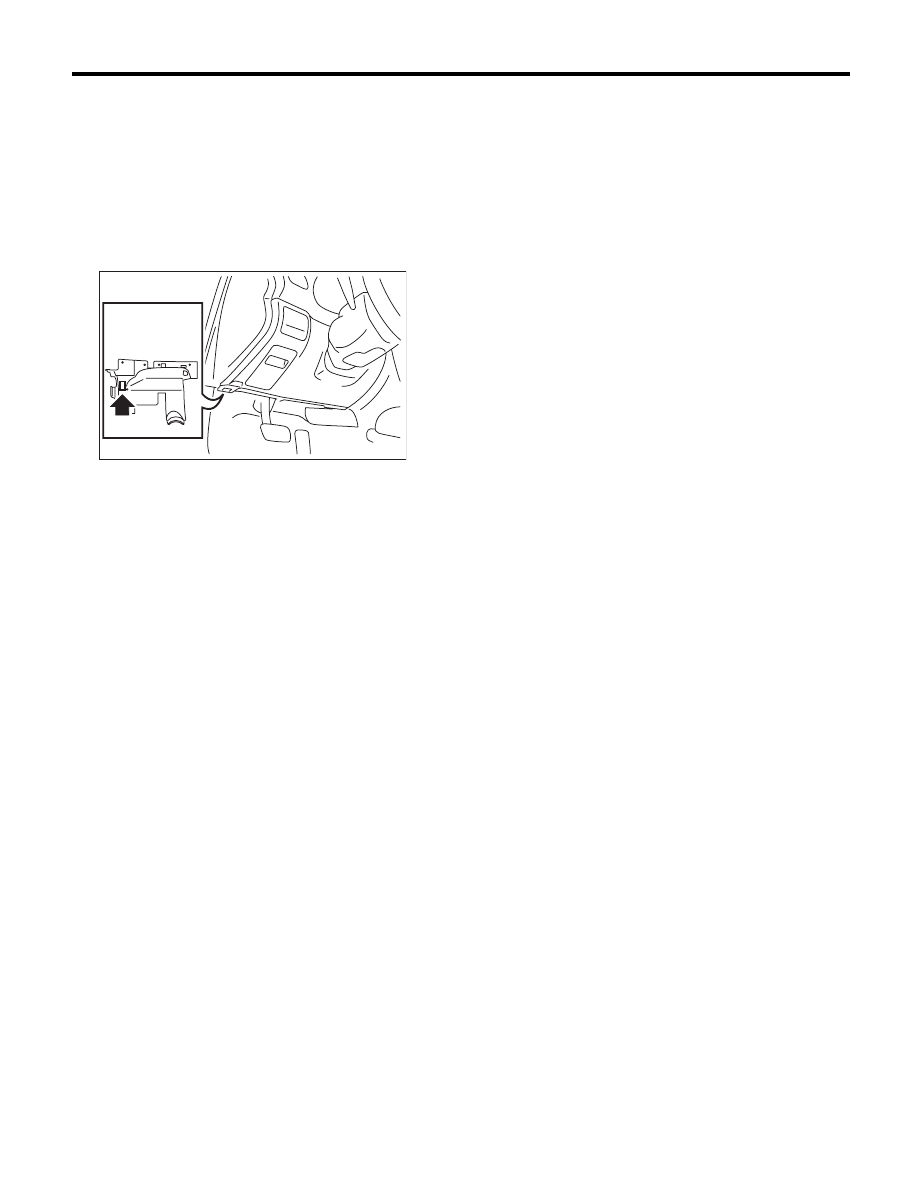
2) Open the cover and connect the general scan
tool to the data link connector located in the lower
area of instrument panel (on the driver’s side).
3) Using the general scan tool, call up DTC and
freeze frame data.
General scan tool functions consist of:
(1) MODE $01: Current powertrain diagnostic
data
(2) MODE $02: Powertrain freeze frame data
(3) MODE $03: Emission-related powertrain
DTC
(4) MODE $04: Clear/Reset emission-related
diagnostic information
(5) MODE $06: Request on-board monitoring
test results for intermittently monitored systems
(6) MODE $07: Request on-board monitoring
test results for continuously monitored systems
(7) MODE $09: Request vehicle information
Read out the data according to repair proce-
dures. (For detailed operation procedure, refer
to the general scan tool operation manual.)
NOTE:
For details concerning DTC, refer to “List of Diag-
nostic Trouble Code (DTC)”. <Ref. to
EN(H6DO)(diag)-81, List of Diagnostic Trouble
Code (DTC).>
EN-02533

EN(H6DO)(diag)-30
General Scan Tool
ENGINE (DIAGNOSTICS)
2. MODE $01 (CURRENT POWERTRAIN DIAGNOSTIC DATA)
Refer to data denoting the current operating condition of analog input/output, digital input/output or the pow-
ertrain system.
A list of the support data and PID (Parameter Identification) codes are shown in the following table.
PID
Data
Unit of measure
$01
Number of emission-related powertrain DTC and malfunction indicator light status
—
$03
Fuel system control status
—
$04
Calculated engine load value
%
$05
Engine coolant temperature
°C
$06
Short term fuel trim (Bank 1)
%
$07
Long term fuel trim (Bank 1)
%
$08
Short term fuel trim (Bank 2)
%
$09
Long term fuel trim (Bank 2)
%
$0B
Intake manifold absolute pressure
kPa
$0C
Engine speed
rpm
$0D
Vehicle speed
MPH
$0E
Ignition timing advance
°
$0F
Intake air temperature
°C
$10
Air flow rate of manifold absolute pressure sensor
g/s
$11
Throttle valve absolute opening angle
%
$13
Check whether oxygen sensor is installed.
—
$15
Oxygen sensor output voltage (Bank 1 Sensor 2)
V
$15
Oxygen sensor compensation (Bank 1 Sensor 2)
%
$19
Oxygen sensor output voltage (Bank 2 Sensor 2)
V
$19
Oxygen sensor compensation (Bank 2 Sensor 2)
%
$1C
On-board diagnostic system
—
$1F
Elapsed time after starting the engine
sec
$21
Travel distance after the malfunction indicator light illuminates
miles
$24
Oxygen sensor output voltage and short term fuel trim associated with oxygen sensor (bank 1)
– and V
$28
Oxygen sensor output voltage and short term fuel trim associated with oxygen sensor (bank 2)
– and V
$2C
Target EGR
%
$2D
EGR deviation
%
$2E
Evaporative purge
%
$2F
Fuel level
%
$30
Number of warm ups after DTC clear
—
$31
Travel distance after DTC clear
miles
$32
Fuel tank pressure
Pa
$33
Atmospheric pressure
kPa
$34
A/F sensor lambda value (Bank 1 Sensor 1)
—
$34
A/F sensor current value (Bank 1 Sensor 1)
mA
$38
A/F sensor lambda value (Bank 2 Sensor 1)
—
$38
A/F sensor current value (Bank 2 Sensor 1)
mA
$3C
Catalyst temperature #1
°C
$3D
Catalyst temperature #2
°C
$41
Diagnosis monitoring per drive cycle
—
$42
ECM power supply voltage
V
$43
Absolute load
%
$44
A/F target lambda
—
$45
Relative throttle opening angle
%
$46
Ambient temperature
°C
$47
Absolute throttle opening angle 2
%
$49
Absolute accelerator opening angle 1
%
$4A
Absolute accelerator opening angle 2
%

EN(H6DO)(diag)-31
General Scan Tool
ENGINE (DIAGNOSTICS)
NOTE:
Refer to general scan tool manufacturer’s instruction manual to access generic OBD-II PIDs (MODE $01).
3. MODE $02 (POWERTRAIN FREEZE FRAME DATA)
Refer to data denoting the operating condition when trouble is sensed by the on-board diagnosis system.
A list of the support data and PID (Parameter Identification) codes are shown in the following table.
NOTE:
Refer to general scan tool manufacturer’s operation manual to access freeze frame data (MODE $02).
$4C
Target throttle opening angle
%
$4D
Engine operating time while malfunction indicator light
min
$4E
Elapsed time after DTC clear
min
$51
Fuel used
—
$5A
Relative acceleration opening angle
%
PID
Data
Unit of measure
$02
DTC that caused the freeze frame data storage required by CARB
—
$03
Fuel system control status
—
$04
Calculated engine load value
%
$05
Engine coolant temperature
°C
$06
Short term fuel trim (Bank 1)
%
$07
Long term fuel trim (Bank 1)
%
$08
Short term fuel trim (Bank 2)
%
$09
Long term fuel trim (Bank 2)
%
$0B
Intake manifold absolute pressure
kPa
$0C
Engine speed
rpm
$0D
Vehicle speed
MPH
$0E
Ignition timing advance
°
$0F
Intake air temperature
°C
$10
Air flow rate of manifold absolute pressure sensor
g/s
$11
Throttle valve opening angle
%
$13
Air fuel ratio sensor
—
$15
Oxygen sensor output voltage (Bank 1 Sensor 2)
V
$15
Oxygen sensor compensation (Bank 1 Sensor 2)
%
$19
Oxygen sensor output voltage (Bank 2 Sensor 2)
V
$19
Oxygen sensor compensation (Bank 2 Sensor 2)
%
$1C
On-board diagnostic system
—
$1F
Elapsed time after starting the engine
sec
$2C
Target EGR
%
$2D
EGR deviation
%
$2E
Evaporative purge
%
$2F
Fuel level
%
$32
Fuel tank pressure
Pa
$33
Atmospheric pressure
kPa
$42
ECM power supply voltage
V
$43
Absolute load
%
$44
A/F target lambda
—
$45
Relative throttle opening angle
%
$46
Ambient temperature
°C
$47
Absolute throttle opening angle 2
%
$49
Absolute accelerator opening angle 1
%
$4A
Absolute accelerator opening angle 2
%
$4C
Target throttle opening angle
%
PID
Data
Unit of measure

EN(H6DO)(diag)-32
General Scan Tool
ENGINE (DIAGNOSTICS)
4. MODE $03 (EMISSION-RELATED POWERTRAIN DTC)
Refer to “List of Diagnostic Trouble Code (DTC)” for information about data denoting emission-related pow-
ertrain DTC. <Ref. to EN(H6DO)(diag)-81, List of Diagnostic Trouble Code (DTC).>
5. MODE $04 (CLEAR/RESET EMISSION-RELATED DIAGNOSTIC INFORMATION)
Refer to the mode used to clear or reset emission-related diagnostic information (OBD-II trouble diagnostic
information).
NOTE:
Refer to general scan tool manufacturer’s instruction manual to clear the emission-related diagnostic infor-
mation (MODE $04).
6. MODE $06
Refer to test value of troubleshooting and data of test limit indicated on the support data bit sequence table.
A list of the support data is shown in the following table.
OBDMID
TID
SID
Diagnostic item
$01
$81
$0A
A/F sensor conduction abnormal (Bank 1 Sensor 1)
$82
$8D
$83
$14
$84
$1E
A/F sensor range abnormal (Bank 1 Sensor 1)
$85
$1E
$86
$20
A/F sensor response abnormal (Bank 1 Sensor 1)
$02
$87
$0B
Oxygen sensor circuit abnormal (Bank 1 Sensor 2)
$88
$0B
$07
$0B
Oxygen sensor drop abnormal (Bank 1 Sensor 2)
$08
$0B
$A5
$0B
$05
$10
Oxygen sensor response abnormal (Bank 1 Sensor 2)
$06
$10
$05
$81
$0A
A/F sensor conduction abnormal (Bank 2 Sensor 1)
$82
$8D
$83
$14
$84
$1E
A/F sensor range abnormal (Bank 2 Sensor 1)
$85
$1E
$86
$20
A/F sensor response abnormal (Bank 2 Sensor 1)
$06
$87
$0B
Oxygen sensor circuit abnormal (Bank 2 Sensor 2)
$88
$0B
$07
$0B
Oxygen sensor drop abnormal (Bank 2 Sensor 2)
$08
$0B
$A5
$0B
$05
$10
Oxygen sensor response abnormal (Bank 2 Sensor 2)
$06
$10
$21
$89
$20
Catalyst degradation diagnosis (Bank 1)
$31
$8A
$FD
EGR system diagnosis
$39
$93
$FE
Evaporative emission control system (Cap off)
$3B
$94
$FE
Evaporative emission control system (0.04 inch leak)
$95
$FE
$3C
$96
$FE
Evaporative emission control system (0.02 inch leak)
$97
$FE
$3D
$98
$FE
Evaporative emission control system (Purge flow)
$41
$99
$24
A/F sensor heater abnormal (Bank 1 Sensor 1)
$9A
$24
$9B
$14
A/F sensor heater characteristic abnormal (Bank 1 Sensor 1)
Нет комментариевНе стесняйтесь поделиться с нами вашим ценным мнением.
Текст