Subaru Legacy IV (2008 year). Service manual — part 1159

CC(diag)-18
Diagnostic Procedure with Cancel Code
CRUISE CONTROL SYSTEM (DIAGNOSTICS)
Step
Check
Yes
No
1
CHECK CLUTCH SWITCH CIRCUIT.
1) Turn the ignition switch to OFF.
2) Disconnect the clutch switch harness con-
nector.
3) Turn the ignition switch to ON.
4) Measure the voltage between harness con-
nector terminal and chassis ground.
Connector & terminal
(B107) No. 1 (+) — Chassis ground (–):
Is the voltage 10 V or more?
Go to step 2.
• Check fuse No. 4
(in fuse & relay
box).
• Check open or
shorted circuit of
harness between
clutch switch and
fuse & relay box.
2
CHECK CLUTCH SWITCH CIRCUIT.
1) Turn the ignition switch to OFF.
2) Disconnect the harness connector of ECM.
3) Measure the resistance between clutch
switch harness connector terminal and ECM
harness connector terminal.
Connector & terminal
(B107) No. 2 — (B136) No. 25:
Is the resistance less than 10
:? Go to step 3.
Repair the har-
ness.
3
CHECK CLUTCH SWITCH.
Remove and check the clutch switch. <Ref. to
CC-8, Clutch Switch.>
Is clutch switch OK?
Replace the ECM.
<Ref. to
FU(H4SO)-39,
Engine Control
Module (ECM).>
<Ref. to
FU(H4DOTC)-52,
Engine Control
Module (ECM).>
<Ref. to
FU(H6DO)-38,
Engine Control
Module (ECM).>
Replace the clutch
switch.
CC(diag)-19
Diagnostic Procedure with Cancel Code
CRUISE CONTROL SYSTEM (DIAGNOSTICS)
D: 14
Detected when select lever is set in the neutral position, or when malfunction related to neutral position
switch occurs.
TROUBLE SYMPTOM:
Cruise control cannot be set.
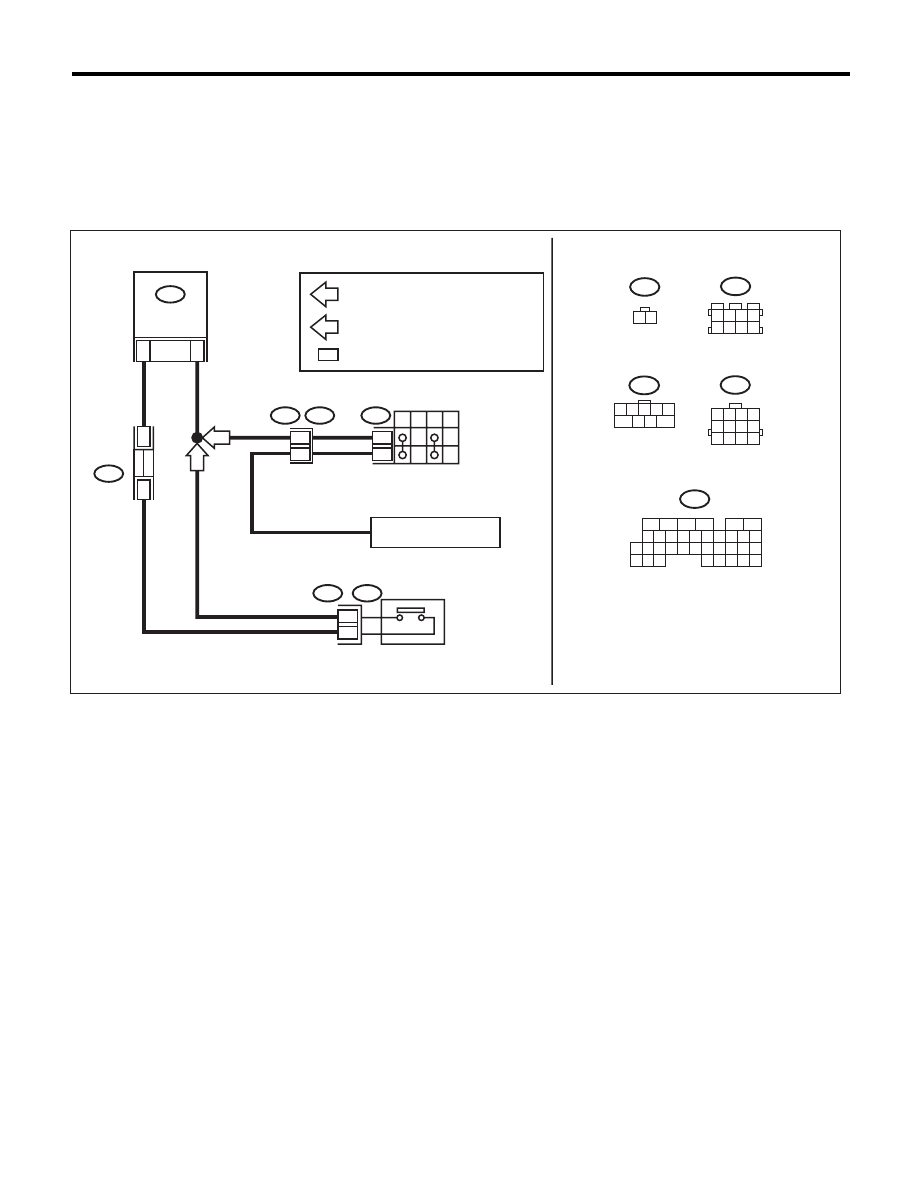
WIRING DIAGRAM:
• 2.5 L non-turbo model
CC-00685
6
B122
3 4
7 8
1 2
5 6
B12
3 4
7 8
1 2
5 6
11 12
9 10
B136
9
30
29
2
3
8
2
31
20
19
18
22
21
10
12
11
14
24
34
33
27
26
16
1
2
3
4
5
6
13
23
15
25
8
7
17
35
B136
B12
T3
T7
B122
B25
ECM
2
1
P
R
N
D
6
9
1 2
B25
31
AT
MT
*
*
12
11
[ST(N4)-01]
AT
: AT MODEL
MT
: MT MODEL
*
:
T2
REF. TO STARTER SYSTEM
T7
1 2 3 4 5
6
7 8
9
JOINT
CONNECT
OR
TERMINAL No. OPTIONAL ARRANGEMENT
INHIBITOR SWITCH
NEUTRAL POSITION SWITCH
CC(diag)-20
Diagnostic Procedure with Cancel Code
CRUISE CONTROL SYSTEM (DIAGNOSTICS)
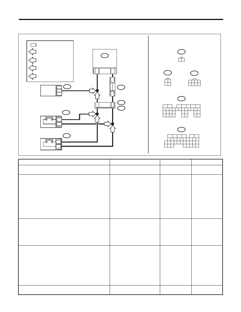
• 2.5L turbo model
• 3.0 L model
Step
Check
Yes
No
1
CHECK VEHICLE FOR SPECIFICATION.
Check the destination and vehicle specification.
Is the vehicle 5AT model?
Go to step 2.
Go to step 5.
2
CHECK NEUTRAL POSITION SWITCH.
1) Connect the Subaru Select Monitor to data
link connector.
2) Turn the ignition switch to ON and run the
Subaru Select Monitor.
3) Select {Engine Control System} from the
main menu.
4) Then, select the {Current Data Display & Save}.
5) Check the neutral position switch signal by
shifting the select lever to “P” or “N” range.
If the select lever is in the “P” or
the “N” range, is the Subaru
Select Monitor Display ON? Or,
if in a range other than “P” or
“N”, is the Subaru Select Moni-
tor display OFF?
Replace the ECM.
<Ref. to
FU(H4DOTC)-52,
Engine Control
Module (ECM).>
<Ref. to
FU(H6DO)-38,
Engine Control
Module (ECM).>
Go to step 3.
3
CHECK TCM OUTPUT VOLTAGE.
1) Turn the ignition switch to ON.
2) Measure the voltage between TCM harness
connector terminal and chassis ground.
Connector & terminal
(B55) No. 11 (+) — Chassis ground (–):
If the select lever is in a range
other than “P” or “N” ranges, is
the voltage 10V or higher? Or, if
in “P” or “N”, is the voltage less
than 1V?
Go to step 4.
Check the TCM.
<Ref. to 5AT(diag)-
2, Basic Diagnostic
Procedure.>
4
CHECK HARNESS BETWEEN TCM AND ECM.
1) Turn the ignition switch to OFF.
2) Disconnect the harness connector from
TCM and ECM.
3) Measure the resistance between TCM har-
ness connector terminal and ECM harness con-
nector terminal.
Connector & terminal
(B136) No. 31 — (B55) No. 11:
Is the resistance less than 10
:? Replace the ECM.
<Ref. to
FU(H4DOTC)-52,
Engine Control
Module (ECM).>
<Ref. to
FU(H6DO)-38,
Engine Control
Module (ECM).>
Repair the wiring
harness.
5
CHECK TRANSMISSION TYPE.
Is the transmission type 4AT?
Go to step 6.
MT model:Go to
step 9.
CC-00686
B136
B55
T12
T9
B128
ECM
TCM
1 2
3 4
B128
31
AT
2
1
11
B55
B136
9
30
29
28
32
31
20
19
18
22
21
10
12
11
14
24
34
33
27
26
16
1
2
3
4
5
6
13
23
15
25
8
7
17
35
5M
5M
T12
1
2
6M
MT
6M
3
1
*
*
B122
6M
:
5M
:
1 2 3 4
5 6 7 8
B122
1 2
T12
6
AT
:
MT
:
*
:
5
6
7
8
2
1
9
4
3
10
24
22 23
25
11 12 13 14 15
26 27
28
16 17 18 19
20 21
29 30 31
32 33
34 35
AT MODEL
5MT MODEL
6MT MODEL
MT MODEL
NEUTRAL
POSITION SWITCH
NEUTRAL
POSITION SWITCH
TERMINAL No. OPTIONAL
ARRANGEMENT

CC(diag)-21
Diagnostic Procedure with Cancel Code
CRUISE CONTROL SYSTEM (DIAGNOSTICS)
6
CHECK INHIBITOR SWITCH CIRCUIT.
1) Turn the ignition switch to OFF.
2) Disconnect the inhibitor switch harness con-
nector.
3) Turn the ignition switch to ON.
4) Measure the voltage between harness con-
nector terminal and chassis ground.
Connector & terminal
(T7) No. 9 (+) — Chassis ground (–):
Is the voltage 10 V or more?
Go to step 7.
Check for open or
short in the har-
ness between
inhibitor switch and
ECM.
7
CHECK INHIBITOR SWITCH CIRCUIT.
1) Turn the ignition switch to OFF.
2) Disconnect the starter motor harness con-
nector.
3) Measure the resistance between inhibitor
switch harness connector terminal and starter
motor.
Connector & terminal
(T7) No. 6 — Starter motor:
Is the resistance less than 10
:? Go to step 8.
Repair the har-
ness.
8
CHECK INHIBITOR SWITCH.
Remove and check the inhibitor switch. <Ref. to
CC-9, Inhibitor Switch.>
Is the inhibitor switch OK?
Replace the ECM.
<Ref. to
FU(H4SO)-39,
Engine Control
Module (ECM).>
Replace the inhibi-
tor switch.
9
CHECK NEUTRAL POSITION SWITCH CIRCUIT.
1) Turn the ignition switch to OFF.
2) Disconnect the neutral position switch har-
ness connector.
3) Turn the ignition switch to ON.
4) Measure the voltage between harness con-
nector terminal and chassis ground.
Connector & terminal
5MT model
(T12) No. 1 (+) — Chassis ground (–)
(2.5L turbo model):
(B25) No. 2 (+) — Chassis ground (–)
(2.0L NA model):
6MT model:
(T12) No. 2 (+) — Chassis ground (–):
Is the voltage 10 V or more?
Go to step 10.
Check for open or
short in the har-
ness between neu-
tral position switch
and ECM.
10
CHECK NEUTRAL POSITION SWITCH CIRCUIT.
1) Turn the ignition switch to OFF.
2) Measure resistance between harness con-
nector terminal of neutral position switch and
chassis ground.
Connector & terminal
5MT model:
(T12) No. 2 — Chassis ground (2.5L
turbo model):
(B25) No. 1 — Chassis ground (2.0L NA
model):
6MT model:
(T12) No. 1 — Chassis ground:
Is the resistance less than 10
:? Go to step 11.
Repair the har-
ness.
11
CHECK NEUTRAL POSITION SWITCH.
Remove and check the neutral position switch.
<Ref. to CC-11, Neutral Position Switch.>
Is the neutral position switch
OK?
Replace the ECM.
<Ref. to
FU(H4SO)-39,
Engine Control
Module (ECM).>
<Ref. to
FU(H4DOTC)-52,
Engine Control
Module (ECM).>
Replace the neu-
tral position switch.
Step
Check
Yes
No
Нет комментариевНе стесняйтесь поделиться с нами вашим ценным мнением.
Текст