Subaru Legacy IV (2008 year). Service manual — part 1158

CC(diag)-14
Diagnostic Procedure with Cancel Code
CRUISE CONTROL SYSTEM (DIAGNOSTICS)
Step
Check
Yes
No
1
CHECK CRUISE CONTROL COMMAND
SWITCH CIRCUIT.
1) Remove the driver’s airbag module. <Ref. to
AB-14, REMOVAL, Driver’s Airbag Module.>
2) Disconnect the harness connector of cruise
control command switch.
3) Turn the ignition switch to ON.
4) Measure the voltage between harness con-
nector terminal and chassis ground.
Connector & terminal
(ST3) No. 8 (+) — Chassis ground (–):
(ST3) No. 7 (+) — Chassis ground (–):
Is the voltage 5 V or more?
Go to step 2.
Check for open,
shorted circuit, or
poor contact of
harness between
cruise control com-
mand switch and
ECM and steering
roll connector.
2
CHECK CRUISE CONTROL COMMAND
SWITCH CIRCUIT.
1) Turn the ignition switch to OFF.
2) Remove the cruise control command
switch. <Ref. to CC-5, REMOVAL, Cruise Con-
trol Command Switch.>
3) Measure the resistance between harness
connector terminal and chassis ground.
Connector terminal
(ST3) No. 6 — Chassis ground:
Is the resistance less than 10
:? Go to step 3.
Check for open
between cruise
control command
switch and ECM
and chassis
ground, and check
the ECM.
3
CHECK CRUISE CONTROL COMMAND
SWITCH.
Measure the resistance between switch termi-
nals when the cruise control command switch is
not depressed.
Terminals
No. 6 — No. 7:
Is the resistance approx. 4 k
:? Go to step 4.
Replace the cruise
control command
switch.
<Ref. to CC-5,
Cruise Control
Command
Switch.>
4
CHECK CANCEL SWITCH.
1) Turn the ignition switch to OFF.
2) Remove the cruise control command
switch. <Ref. to CC-5, REMOVAL, Cruise Con-
trol Command Switch.>
3) Measure the resistance between switch ter-
minals with the CANCEL switch pressed.
Terminals
No. 6 — No. 7:
Is the resistance approx. less
than 1
: when the CANCEL
switch is pressed?
Go to step 5.
Replace the cruise
control command
switch.
<Ref. to CC-5,
Cruise Control
Command
Switch.>
5
CHECK SET/COAST SWITCH.
Measure the resistance between switch termi-
nals with the SET/COAST switch pressed.
Terminals
No. 6 — No. 7:
Is the resistance approx. 250
:
when SET/COAST switch is
pressed?
Go to step 6.
Replace the cruise
control command
switch. <Ref. to
CC-5, Cruise Con-
trol Command
Switch.>
6
CHECK RESUME/ACCEL SWITCH CIRCUIT.
Measure the resistance between switch termi-
nals when the RESUME/ACCEL switch is
pressed.
Terminals
No. 6 — No. 7:
Is the resistance approx. 1,500
:
when RESUME/ACCEL switch
is pressed?
Replace the ECM.
<Ref. to
FU(H4SO)-39,
Engine Control
Module (ECM).>
<Ref. to
FU(H4DOTC)-52,
Engine Control
Module (ECM).>
<Ref. to
FU(H6DO)-38,
Engine Control
Module (ECM).>
Replace the cruise
control command
switch. <Ref. to
CC-5, Cruise Con-
trol Command
Switch.>
CC(diag)-15
Diagnostic Procedure with Cancel Code
CRUISE CONTROL SYSTEM (DIAGNOSTICS)
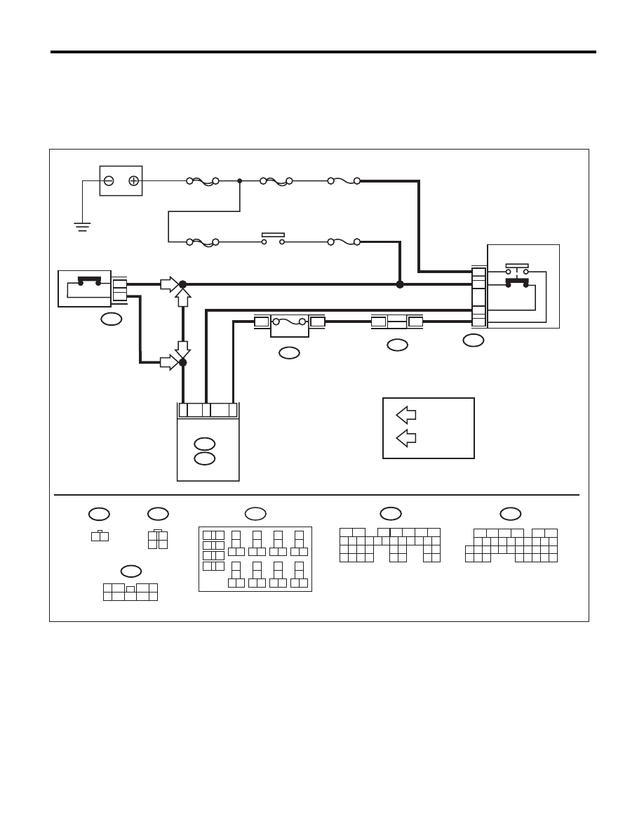
B: 12
The DTC is detected when the brake pedal is pressed or problem relating to stop light & brake switch occurs.
TROUBLE SYMPTOM:
• Cruise control cannot be set.
• Cruise control cannot be released.
WIRING DIAGRAM:
MAIN SBF
SBF-2
SBF-8
F/B No. 8
F/B No. 4
B65
4
3
1
2
B65
1
2
3
4
B28
B20
C25
B135
B:
B136
C:
ECM
B136
9
30
29
2
3
8
2
31
20
19
18
22
21
10
12
11
14
24
34
33
27
26
16
1
2
3
4
5
6
13
23
15
25
8
7
17
35
C:
5
B159
9
9
4
7
6
2
1
5
3
8
B159
B135
5
6
7
8
2
1
9
4
3
10
24
22 23
25
11 12 13 14 15
26 27
28
16 17 18 19
20 21
29 30 31
32 33
34 35
B:
B225
AT
: AT MODEL
MT
: MT MODEL
4
3
B225
CC-00684
2
1
B107
AT
AT
MT
13
14
15 16
17
27
24
25
26
20
21
22
23
29
30
31
28
32
35
33
34
37
38
39
36
40
8
9
10
11 12
1
2
5
3
4
7
6
19
18
B107
1 2
7.5A
FUSE & RELAY BOX
MT
BATTERY
IGNITION
RELAY
RELAY BOX
RELAY BLOCK
CLUTCK SWITCH (MT)
STOP LIGHT SWITCH
AND BRAKE SWITCH
STOP LIGHT
SWITCH
BRAKE
SWITCH

CC(diag)-16
Diagnostic Procedure with Cancel Code
CRUISE CONTROL SYSTEM (DIAGNOSTICS)
Step
Check
Yes
No
1
CHECK STOP LIGHT & BRAKE SWITCH
CIRCUIT.
1) Turn the ignition switch to OFF.
2) Disconnect the stop light & brake switch har-
ness connector.
3) Turn the ignition switch to ON.
4) Measure the voltage between harness con-
nector terminal and chassis ground.
Connector & terminal
(B65) No. 2 (+) — Chassis ground (–):
Is the voltage 10 V or more?
Go to step 2.
• Check fuse No. 8
(in fuse & relay
box).
• Check for open
or short circuit in
the harness
between stop light
& brake switch and
fuse & relay box.
2
CHECK STOP LIGHT & BRAKE SWITCH
CIRCUIT.
Measure the voltage between harness connec-
tor terminal and chassis ground.
Connector & terminal
(B65) No. 4 (+) — Chassis ground (–):
Is the voltage 10 V or more?
Go to step 3.
• Check fuse No. 4
(in fuse & relay
box).
• Check for open
or short in the har-
ness between stop
light & brake switch
and fuse & relay
box.
3
CHECK STOP LIGHT & BRAKE SWITCH
CIRCUIT.
1) Turn the ignition switch to OFF.
2) Disconnect the harness connector of ECM.
3) Measure the resistance between ECM har-
ness connector terminal and stop light & brake
switch harness connector terminal.
Connector & terminal
(B135) No. 28 — (B65) No. 3:
(B135) No. 20 — (B65) No. 1:
Is the resistance less than 10
:? Go to step 4.
Repair the har-
ness.
4
CHECK STOP LIGHT & BRAKE SWITCH
CIRCUIT.
Remove and check the stop light & brake
switch. <Ref. to CC-7, Stop Light & Brake
Switch.>
Is the stop light & brake switch
OK?
Replace the ECM.
<Ref. to
FU(H4SO)-39,
Engine Control
Module (ECM).>
<Ref. to
FU(H4DOTC)-52,
Engine Control
Module (ECM).>
<Ref. to
FU(H6DO)-38,
Engine Control
Module (ECM).>
Replace the stop
light & brake
switch.

CC(diag)-17
Diagnostic Procedure with Cancel Code
CRUISE CONTROL SYSTEM (DIAGNOSTICS)
C: 13
The DTC is detected when the clutch pedal is depressed or problem relating to the clutch switch occurs.
TROUBLE SYMPTOM:
• Cruise control cannot be set.
• Cruise control cannot be released.
WIRING DIAGRAM:
MAIN SBF
SBF-2
SBF-8
F/B No. 8
F/B No. 4
B65
4
3
1
2
B65
1
2
3
4
B28
B20
C25
B135
B:
B136
C:
ECM
B136
9
30
29
2
3
8
2
31
20
19
18
22
21
10
12
11
14
24
34
33
27
26
16
1
2
3
4
5
6
13
23
15
25
8
7
17
35
C:
5
B159
9
9
4
7
6
2
1
5
3
8
B159
B135
5
6
7
8
2
1
9
4
3
10
24
22 23
25
11 12 13 14 15
26 27
28
16 17 18 19
20 21
29 30 31
32 33
34 35
B:
B225
AT
: AT MODEL
MT
: MT MODEL
4
3
B225
CC-00684
2
1
B107
AT
AT
MT
13
14
15 16
17
27
24
25
26
20
21
22
23
29
30
31
28
32
35
33
34
37
38
39
36
40
8
9
10
11 12
1
2
5
3
4
7
6
19
18
B107
1 2
7.5A
FUSE & RELAY BOX
MT
BATTERY
IGNITION
RELAY
RELAY BOX
RELAY BLOCK
CLUTCK SWITCH (MT)
STOP LIGHT SWITCH
AND BRAKE SWITCH
STOP LIGHT
SWITCH
BRAKE
SWITCH
Нет комментариевНе стесняйтесь поделиться с нами вашим ценным мнением.
Текст