Subaru Legacy IV (2008 year). Service manual — part 1091
IDI-5
Combination Meter System
INSTRUMENTATION/DRIVER INFO
2. Combination Meter System
A: WIRING DIAGRAM
1. COMBINATION METER
<Ref. to WI-166, WIRING DIAGRAM, Combination Meter System.>
B: INSPECTION
1. SELF-DIAGNOSIS
The self-diagnosis (checking of each meter, warning light, indicator, illumination, LCD, buzzer sound) of com-
bination meter can be performed in the following procedure.
NOTE:
Perform the steps described in 2) through 4) within 10 seconds.
1) Within 3 seconds after turning the ignition switch to ON, set the lighting switch to tail light or headlight po-
sition.
2) Press the odo/trip meter knob three times.
3) Turn the lighting switch to OFF, and press the odo/trip meter knob three times.
4) Set the lighting switch to tail light or headlight position again, and press the odo/trip meter knob three
times.
NOTE:
• When pressing the odo/trip meter knob four times, the display changes to DTC display mode. <Ref. to IDI-
18, DTC DISPLAY MODE, INSPECTION, Combination Meter System.>
• When the self-diagnosis function operates, the warning light, indicator, and LCD display checks are per-
formed. After this, operation checks are performed in the order of meter, illumination, and buzzer for each
press of the odo/trip meter knob button. <Ref. to IDI-6, LIST OF SELF-DIAGNOSIS MODE OPERATION, IN-
SPECTION, Combination Meter System.> Turn the ignition switch to OFF to cancel the self-diagnosis func-
tion.
• When the engine starts during diagnosis, the self-diagnosis function is not cancelled, however, once the
vehicle starts driving, the self-diagnosis function is deactivated automatically for safety.
IDI-6
Combination Meter System
INSTRUMENTATION/DRIVER INFO
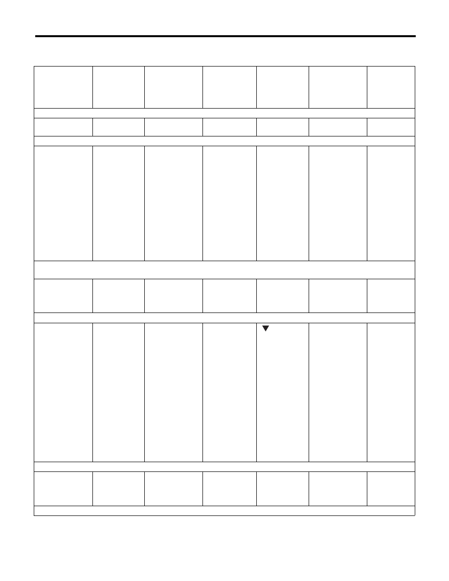
2. LIST OF SELF-DIAGNOSIS MODE OPERATION
Normal meter
Speedometer,
tachometer, fuel
gauge, engine
coolant tempera-
ture gauge
Microcomputer
running type
warning light,
indicator light
AT select lever
position indicator
light
Odo/Trip indica-
tor
SPORT shift
indicator
Illumination
(indicator needle,
plate, ring, LCD)
Buzzer
(SPORT shift
buzzer, VDC
buzzer)
Step 0. Processing to self-diagnosis function
Operating initial
operation
Initial illuminat-
ing
Normal
Normal
Initial illuminat-
ing
Initial illuminating
Not beep.
Step 1-1. Check each indication after initial operation
Repeat the
sweep operation
(After holding on
lowest position for
one second,
reaches to high-
est position within
5 seconds, and
after holding on
highest position
for one second,
reaches to low-
est position within
5 seconds).
Light ON
With the highest
brightness, illumi-
nate the position
sequentially at a
cycle of 1.5 sec-
onds.
Perform the
segment check.
For the illumina-
tion order, refer
to the illumina-
tion order table.
Perform the
segment check.
For the illumi-
nation order,
refer to the illu-
mination order
table.
Light at the high-
est brightness.
Not beep.
Step 1-2. Press the trip knob (trip knob input is not accepted till the meter indicator needle reaches the highest position): sweep
complete, AT select lever position indicator display is set
After completing
sweep in step 1-
1, back to lowest
position.
Light ON
Keep the position
indicated when
the trip knob is
pressed.
Underbar “ _ ” is
displayed.
“1” is displayed.
Light at the high-
est brightness.
Not beep.
Step 2-1. Press the trip knob, and hold it: Check each meter
All meters are
moved simulta-
neously in every
0.5 seconds from
the lowest posi-
tion to highest
position.
Speedometer/
Tachometer:
Approx. 5
degrees at every
movement.
Engine coolant
temperature /Fuel
gauge: Moves
approx. 2
degrees at a time.
Light OFF
Keep the position
indicated that set
in step 1-2.
Display the cur-
rent meter
directing angle
on odometer.
Ex.) When the
speedometer/
tachometer: 135
degrees and
engine coolant
temperature
gauge/fuel
gauge: 54
degrees, dis-
plays “135054”.
“
2” is dis-
played.
Light at the high-
est brightness.
Not beep.
Step 2-2. Release the trip knob: Specifying the meter directing position
Stop at directing
position when the
trip knob is
released.
Light OFF
Keep the position
indicated that set
in step 1-2.
Display the cur-
rent meter
directing angle
on odometer.
“2” is displayed.
Light at the high-
est brightness.
Not beep.
Step 3-1. Press the trip knob, and hold it: Check illumination
IDI-7
Combination Meter System
INSTRUMENTATION/DRIVER INFO
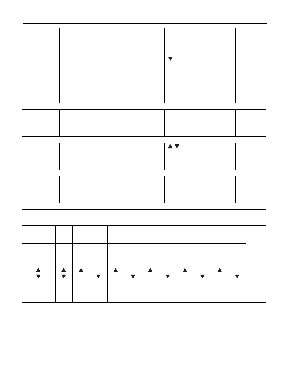
• Illuminating order table
Keep the position
that specified at
step 2-2.
Light OFF
Varying from the
highest bright-
ness (ILL6) to the
lowest lumines-
cence (ILL1)
every second.
After reaching at
ILL1, repeat it
from ILL6.
Illumination
brightness is
displayed.
(From ILL6 to
ILL1)
“
3” is dis-
played.
Varying from the
highest bright-
ness (ILL6) to the
lowest lumines-
cence (ILL1)
every second.
After reaching at
(ILL1), repeat it
from (ILL6).
Not beep.
Step 3-2. Release the trip knob: Specifying the illumination brightness
Keep the position
that specified at
step 2-2.
Light OFF
Keep the bright-
ness at the time
when the trip
knob is released.
Displays the
brightness level
at the time when
the trip knob
was released.
“3” is displayed.
Keep the bright-
ness at the time
when the trip
knob is released.
Not beep.
Step 4-1. Press the trip knob: Check the beeping of SPORT shift buzzer (For AT model)
All meter indica-
tor needle returns
to lowest position.
Light OFF
Light at the high-
est brightness.
Keep the position
indicated that set
in step 1-2.
Illumination
brightness is
displayed.
“
8” is dis-
played. Blinks
with buzzer.
Light at the high-
est brightness.
SPORT shift
buzzer beeps.
Step 4-2. Press the trip knob: Check the VDC indicator light (Model with VDC)
All meter indica-
tor needle returns
to lowest position.
VDC warning
light and VDC
operation indi-
cator light blink.
Light at the high-
est brightness.
Keep the position
indicated that set
in step 1-2.
Illumination
brightness is
displayed.
“4” is displayed.
Light at the high-
est brightness.
VDC buzzer
beeps.
Step 5. Press the trip knob: Complete the self-diagnosis 1 cycle
All meter indicator needle returns to lowest position, and go back to step 1 after completion.
Illuminating
order
1
2
3
4
5
6
7
8
9
10
11
Go back
to 1 and
repeat.
Trip meter A/B
AB
A
B
A
B
A
B
A
B
A
B
Odo/trip meter
8888.8
888888
00000
000000
1111.1
111111
22222
222222
3333.3
333333
44444
444444
5555.5
555555
66666
666666
7777.7
777777
88888
888888
9999.9
999999
SPORT shift
indicator
8
1
2
3
4
5
1
2
3
4
5
AT select lever
position indicator
P
P
R
R
R
N
N
N
D
D
D
Display time
(sec.)
1
0.5
0.5
0.5
0.5
0.5
0.5
0.5
0.5
0.5
0.5
Speedometer,
tachometer, fuel
gauge, engine
coolant tempera-
ture gauge
Microcomputer
running type
warning light,
indicator light
AT select lever
position indicator
light
Odo/Trip indica-
tor
SPORT shift
indicator
Illumination
(indicator needle,
plate, ring, LCD)
Buzzer
(SPORT shift
buzzer, VDC
buzzer)
IDI-8
Combination Meter System
INSTRUMENTATION/DRIVER INFO
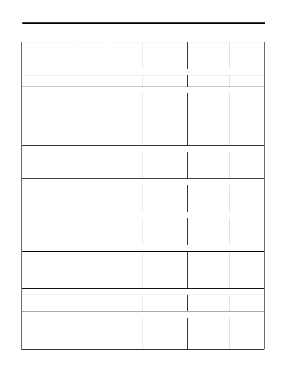
3. LIST OF SELF-DIAGNOSIS MODE OPERATION
Meter with multi-information display
Speedometer, tachome-
ter, fuel gauge, engine
coolant temperature
gauge, ECO gauge
Microcomputer
running type
warning light,
indicator light
AT select lever
position indica-
tor light
Multi-information dis-
play
Illumination
(indicator needle,
plate, ring, LCD)
Buzzer (SPORT
shift buzzer,
VDC buzzer,
vehicle speed
warning buzzer)
Step 0. Processing to self-diagnosis function
Operating initial opera-
tion
Initial illuminating Normal
TRIP: Normal
ODO: Normal
Initial illuminating
Not beep.
Step 1-1. Check each indication after initial operation
Repeat the sweep opera-
tion (After holding on
lowest position for one
second, reaches to high-
est position within 5 sec-
onds, and after holding
on highest position for
one second, reaches to
lowest position within 5
seconds).
Light ON
Perform the
segment check.
For the illumina-
tion order, refer
to the table 1 of
illumination
order tables.
STEP 1 is displayed.
White illumination: 6
seconds.
Yellow illumination: 6
seconds.
Light at the highest
brightness.
Not beep.
Step 1-2. Press the trip knob: sweep completes, AT select lever position indicator display is set
After quitting sweep in
step 1-1, back to lowest
position. (Until back to
lowest position, ignore
trip input.)
Light ON
Keep the posi-
tion indicated
when the trip
knob is pressed.
Keep the illumination
color indicated when
the trip knob is
pressed.
Light at the highest
brightness.
Not beep.
Step 2-1. Press the trip knob, and hold it: Check each meter
Perform the indicator
needle check. For the
illumination order, refer
to the table 2 of illumina-
tion order tables.
Light OFF (Low
fuel warning light
follows the table
2 of tables.)
For the illumina-
tion order, refer
to the table 2 of
illumination
order tables.
STEP 2 is displayed.
White illumination:
12.5 seconds.
Yellow illumination:
12.5 seconds.
Light at the highest
brightness.
Not beep.
Step 2-2. Release the trip knob: Specifying the meter directing position
Stop at directing posi-
tion when the trip knob is
released. (Indicator nee-
dle stops moving after
movement is completed.)
Light OFF
Keep the posi-
tion indicated
when the trip
knob is
released.
Keep the illumination
color at the time when
the trip knob is
released.
Light at the highest
brightness.
Not beep.
Step 3-1. Press the trip knob, and hold it: Check illumination
Keep the position that
specified at step 2-2.
Light OFF
Keep the posi-
tion that speci-
fied at step 2-2.
STEP 3 is displayed,
then illumination
brightness is dis-
played.
(From ILL6 to ILL1)
Varying from the
highest brightness
(ILL6) to the lowest
luminescence (ILL1)
every second. After
reaching at (ILL1),
repeat it from (ILL6).
Not beep.
Step 3-2. Release the trip knob: Specifying the illumination brightness
Keep the position that
specified at step 2-2.
Light OFF
Keep the posi-
tion that speci-
fied at step 2-2.
Keep the position indi-
cated when the trip
knob is pressed.
Keep the brightness
at the time when the
trip knob is released.
Not beep.
Step 4-1. Press the trip knob: Check the beeping of multi buzzer
All meter indicator nee-
dle returns to lowest
position.
Light OFF
P is displayed in
white illumina-
tion.
STEP 3 WN BUZZER
is displayed.
White illumination:
1 second.
Yellow illumination:
1 second.
Light at the highest
brightness.
Buzzer beeps
when multi infor-
mation display is
yellow illumina-
tion.
Нет комментариевНе стесняйтесь поделиться с нами вашим ценным мнением.
Текст