Subaru Legacy IV (2008 year). Service manual — part 67
ME(H4SO)-64
Cylinder Head
MECHANICAL
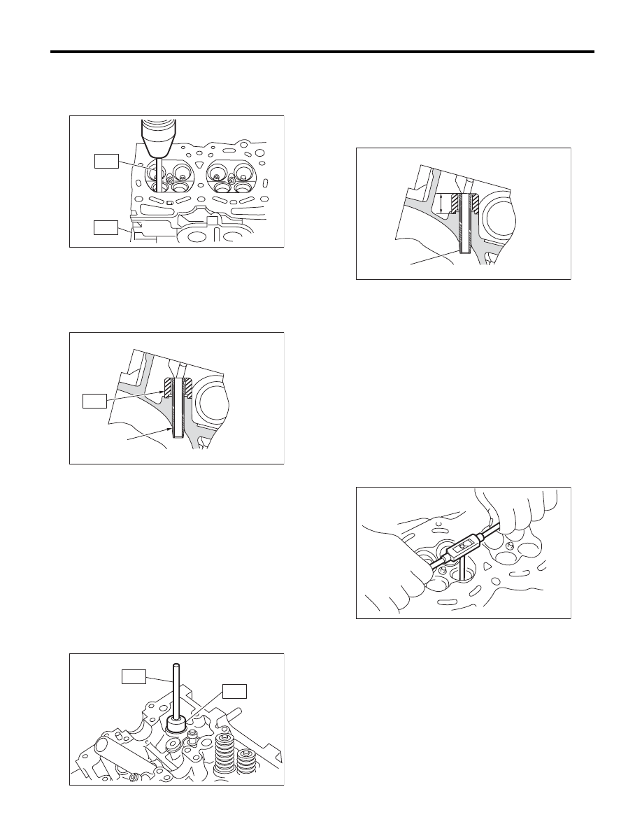
(2) Insert the ST2 into valve guide and press it
down to remove the valve guide.
ST1
498267800
CYLINDER HEAD TABLE
ST2
499767200
VALVE GUIDE REMOVER
(3) Turn the cylinder head upside down and
place the ST as shown in the figure.
Intake side
ST
499767700
VALVE GUIDE ADJUSTER
Exhaust side
ST
499767800
VALVE GUIDE ADJUSTER
(4) Before installing a new valve guide, make sure
that neither scratches nor damages exist on the in-
ner surface of valve guide holes in cylinder head.
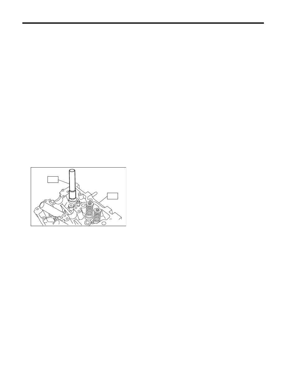
(5) Put a new valve guide, coated with sufficient
oil, in cylinder, and insert the ST1 into valve
guide. Press in until the valve guide upper end
is flush with the upper surface of ST2.
ST1
499767200
VALVE GUIDE REMOVER
Intake side
ST2
499767700
VALVE GUIDE ADJUSTER
Exhaust side
ST2
499767800
VALVE GUIDE ADJUSTER
(6) Check the valve guide protrusion.
Valve guide protrusion L:
Intake
20.0 — 21.0 mm (0.787 — 0.827 in)
Exhaust
16.5 — 17.5 mm (0.650 — 0.689 in)
(7) Ream the inside of valve guide using ST.
Put the ST in valve guide, and rotate the ST
slowly clockwise while pushing it lightly. Bring
the ST back while rotating it clockwise.
NOTE:
• Apply engine oil to the ST when reaming.
• If the inner surface of valve guide is damaged,
the edge of ST should be slightly ground with oil
stone.
• If the inner surface of valve guide becomes lus-
trous and the ST does not chip, use a new ST or
remedy the ST.
ST
499767400
VALVE GUIDE REAMER
(8) After reaming, clean the valve guide to re-
move chips.
(9) Recheck the contact condition between
valve and valve seat after replacing the valve
guide.
(A) Valve guide
ME-00290
ST2
ST1
(A)
ME-00291
ST
ST2
ME-00292
ST1
(A) Valve guide
ME-00293
(A)
L
ME-00294
ME(H4SO)-65
Cylinder Head
MECHANICAL
4. INTAKE AND EXHAUST VALVE
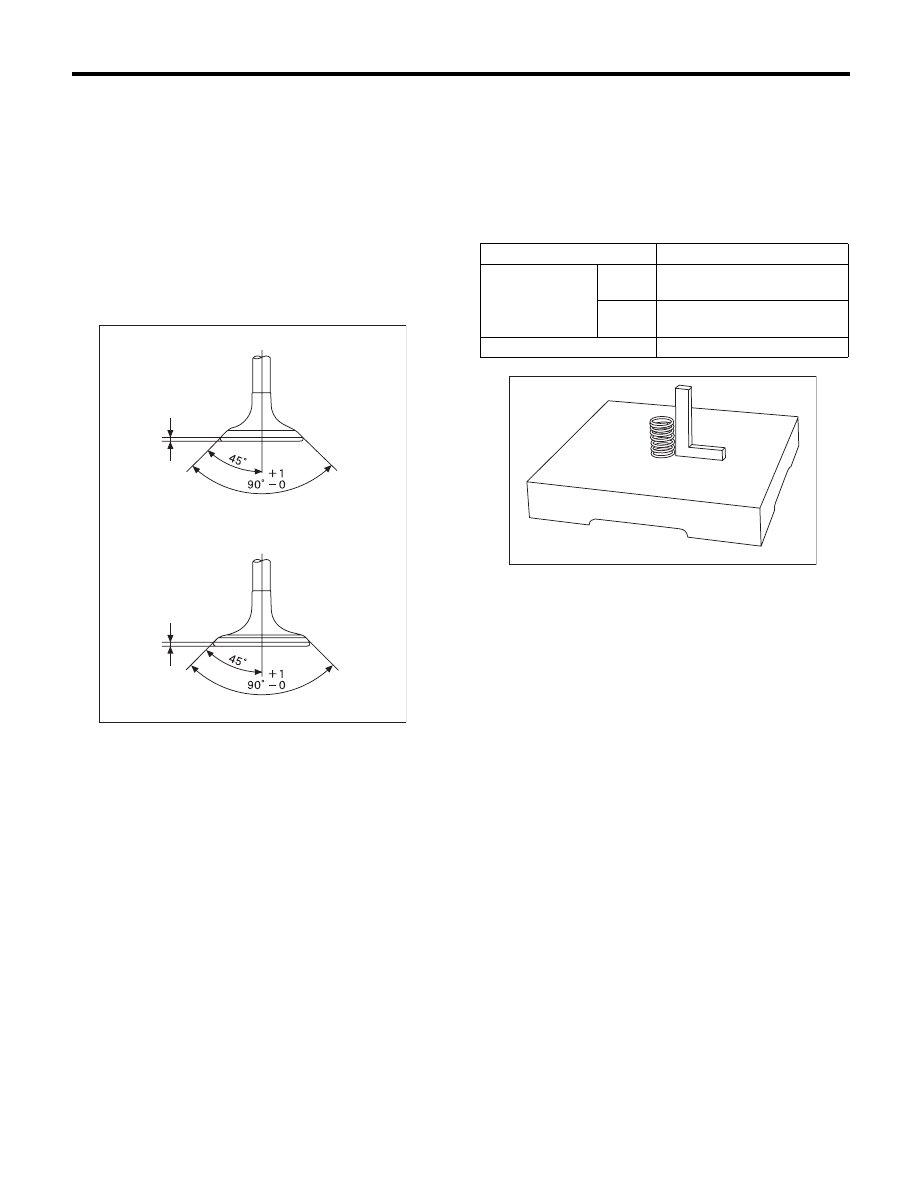
1) Inspect the flange and stem of valve, and re-
place the valve with a new part if damaged, worn,
deformed, or if “H” exceeds the specified limit.
Head edge thickness H:
Intake (A)
Standard:
0.8 — 1.2 mm (0.03 — 0.047 in)
Exhaust (B)
Standard:
1.0 — 1.4 mm (0.039 — 0.055 in)
2) Put a small amount of grinding compound on the
seat surface, and lap the valve and seat surface.
Replace with a new valve oil seal after lapping.
NOTE:
It is possible to differentiate between the intake
valve and the exhaust valve by their overall length.
Valve overall length:
Intake
120.6 mm (4.75 in)
Exhaust
121.7 mm (4.79 in)
5. VALVE SPRING
1) Check the valve springs for damage, free length,
and tension. Replace the valve spring if it is not
within the standard value presented in the table.
2) To measure the squareness of the valve spring,
stand the valve spring on a surface plate and mea-
sure its deflection at the top of the spring using a try
square.
ME-00758
H
H
(B)
(A)
Free length
mm (in) 55.2 (2.173)
Tension/spring
height
N (kgf, lbf)/mm (in)
Set
235.3 — 270.7 (24 — 27.6,
52.9 — 60.8)/45.0 (1.772)
Lift
578.9 — 639.9 (59.1 — 65.3,
130.3 — 143.9)/34.7 (1.366)
Squareness
2.5°, 2.4 mm (0.094 in) or less
ME-00283
ME(H4SO)-66
Cylinder Head
MECHANICAL
6. INTAKE AND EXHAUST VALVE OIL SEAL
1) For the following, replace the oil seal with a new
part.
See the procedure 2) and subsequent for replace-
ment procedures.
• When the lip is damaged.
• When the spring is out of the specified position.
• When readjusting the surfaces of valve and
valve seat.
• When replacing the valve guide.
2) Place the cylinder head on the ST1, and press-fit
the oil seal using the ST2.
ST1
498267800
CYLINDER HEAD TABLE
ST2
498857100
VALVE OIL SEAL GUIDE
NOTE:
• Apply engine oil to oil seal before press-fitting.
• When press-fitting the oil seal, do not use a ham-
mer, etc. or strike in.
• The intake valve oil seals and exhaust valve oil
seals are distinguished by their colors.
Color of rubber part:
Intake [Gray]
Exhaust [Green]
ME-00284
ST1
ST2
ME(H4SO)-67
Cylinder Block
MECHANICAL
21.Cylinder Block
A: REMOVAL
NOTE:
Before conducting this procedure, drain the engine
oil completely.
1) Remove the V-belts. <Ref. to ME(H4SO)-38,
REMOVAL, V-belt.>
2) Remove the intake manifold. <Ref. to
FU(H4SO)-13, REMOVAL, Intake Manifold.>
3) Remove the crank pulley. <Ref. to ME(H4SO)-
41, REMOVAL, Crank Pulley.>
4) Remove the timing belt cover. <Ref. to
ME(H4SO)-43, REMOVAL, Timing Belt Cover.>
5) Remove the timing belt. <Ref. to ME(H4SO)-44,
REMOVAL, Timing Belt.>
6) Remove the crank sprocket. <Ref. to
ME(H4SO)-50, REMOVAL, Crank Sprocket.>
7) Remove the generator and A/C compressor with
their brackets.
8) Remove the cylinder head. <Ref. to ME(H4SO)-
58, REMOVAL, Cylinder Head.>
9) Remove the clutch disc and cover. (MT model)
<Ref. to CL-13, REMOVAL, Clutch Disc and Cov-
er.>
10) Remove the flywheel. (MT model) <Ref. to CL-
16, REMOVAL, Flywheel.>
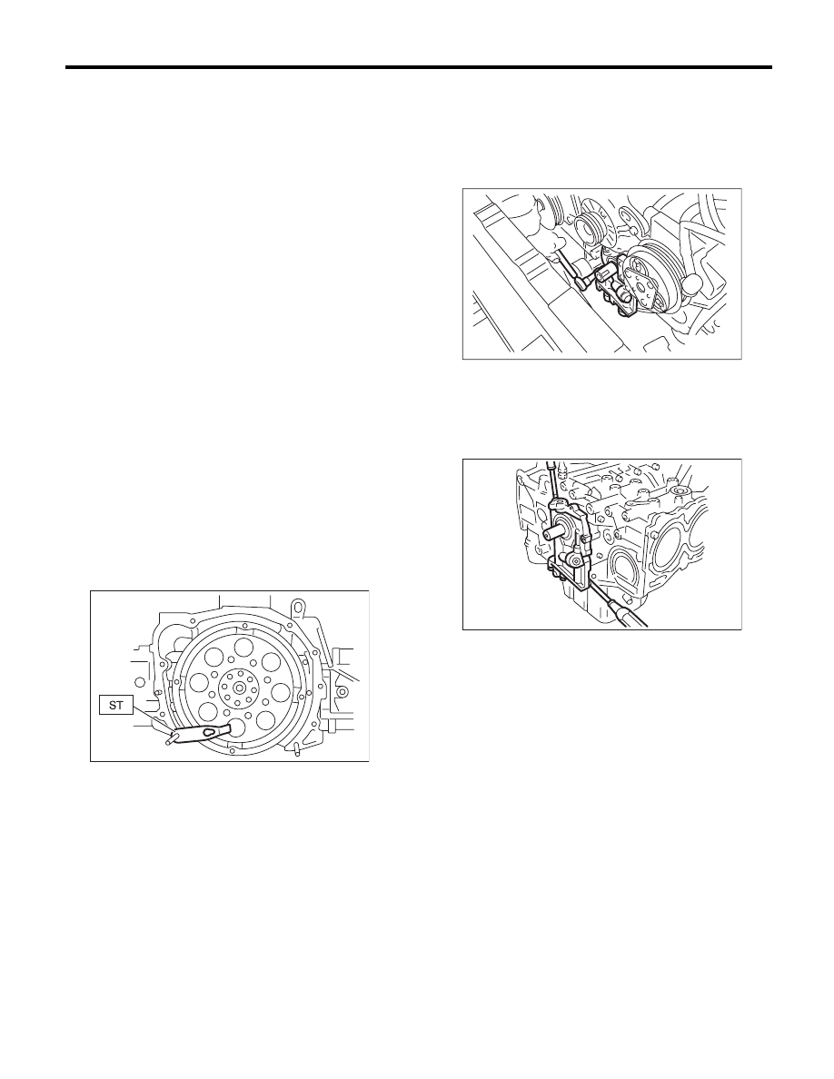
11) Use the ST to lock the crankshaft, and remove
the drive plate. (AT model)
ST
498497100
CRANKSHAFT STOPPER
12) Remove the oil separator cover.
13) Remove the water by-pass pipe for heater.
14) Remove the water pump. <Ref. to CO(H4SO)-
15, REMOVAL, Water Pump.>
15) Remove the bolts which install oil pump onto
cylinder block.
NOTE:
When disassembling and checking the oil pump,
loosen the relief valve plug before removing the oil
pump.
16) Remove the oil pump from cylinder block using
a flat tip screwdriver.
CAUTION:
Be careful not to scratch the mating surface of
cylinder block and oil pump.
17) Remove the front oil seal from the oil pump.
18) Remove the oil pan.
(1) Set the part so that the cylinder block LH is
on the upper side.
(2) Remove the bolts which secure oil pan to
cylinder block.
(3) Insert an oil pan cutter blade between cylin-
der block-to-oil pan clearance and remove the
oil pan.
CAUTION:
Do not use a screwdriver or similar tools in
place of oil pan cutter.
19) Remove the oil strainer.
20) Remove the baffle plate.
21) Remove the oil filter. <Ref. to LU(H4SO)-23,
REMOVAL, Engine Oil Filter.>
ME-00298
LU-00015
ME-00138
Нет комментариевНе стесняйтесь поделиться с нами вашим ценным мнением.
Текст