Subaru Legacy IV (2008 year). Service manual — part 65
ME(H4SO)-56
Camshaft
MECHANICAL
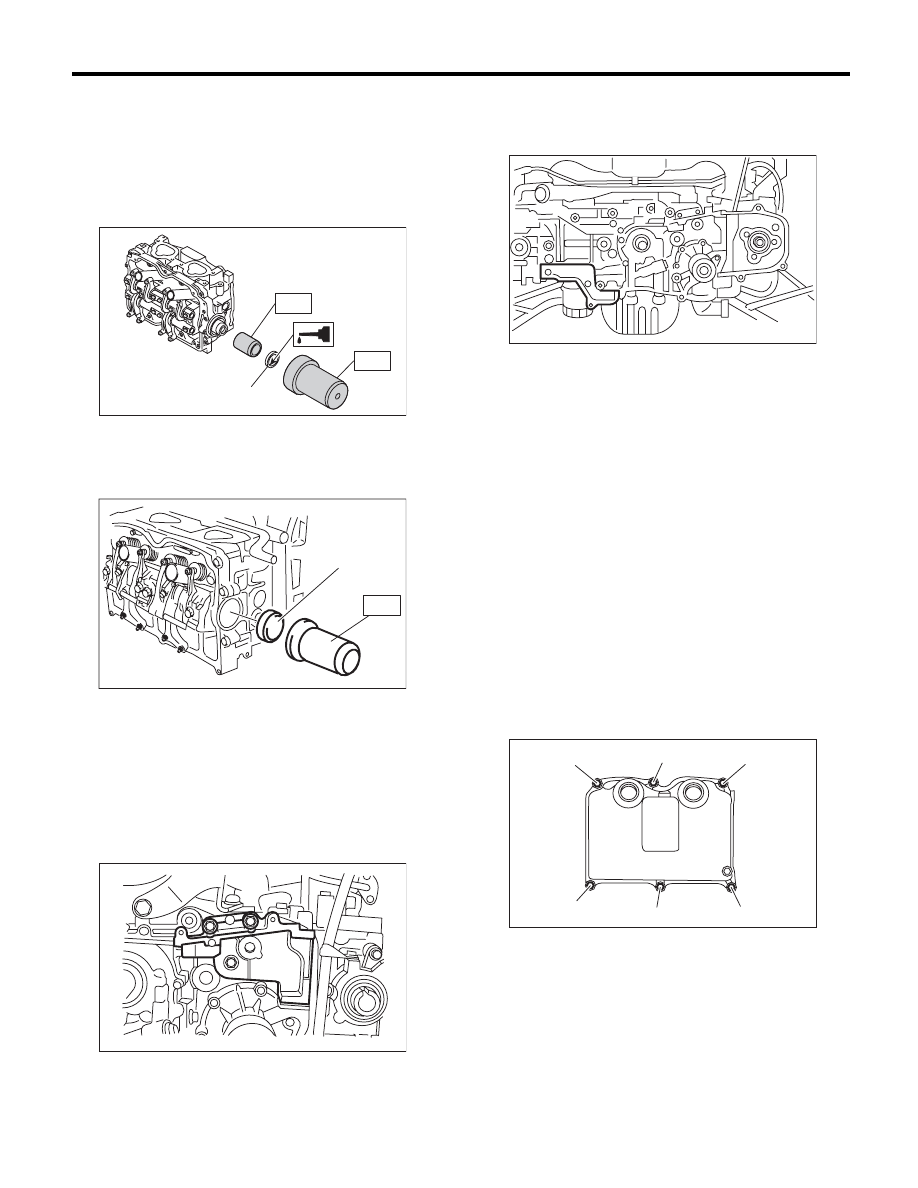
3) Apply a coat of engine oil to camshaft oil seal pe-
riphery and oil seal lips and install the oil seal (A) on
camshaft using ST1 and ST2.
NOTE:
Use a new oil seal.
ST1
499597000
OIL SEAL GUIDE
ST2
499587500
OIL SEAL INSTALLER
4) Apply a coat of engine oil to plug periphery and
Install the plug (A) using ST.
ST
499587700
CAMSHAFT OIL SEAL
INSTALLER
5) Install the camshaft position sensor support. (LH
side only)
Tightening torque:
6.4 N·m (0.7 kgf-m, 4.7 ft-lb)
6) Similarly, install the parts on right-hand side.
7) Install the tensioner bracket.
Tightening torque:
24.5 N·m (2.5 kgf-m, 18.1 ft-lb)
8) Install the timing belt cover No. 2 RH.
Tightening torque:
5 N·m (0.5 kgf-m, 3.7 ft-lb)
9) Install the timing belt cover No. 2 LH.
Tightening torque:
5 N·m (0.5 kgf-m, 3.7 ft-lb)
10) Install the cam sprocket. <Ref. to ME(H4SO)-
49, INSTALLATION, Cam Sprocket.>
11) Install the timing belt. <Ref. to ME(H4SO)-45,
INSTALLATION, Timing Belt.>
12) Adjust the valve clearance. <Ref. to
ME(H4SO)-28, ADJUSTMENT, Valve Clearance.>
13) Install the rocker cover.
(1) Install the rocker cover gasket to the rocker
cover.
NOTE:
Use a new rocker cover gasket.
(2) Temporarily tighten the bolts in alphabetical
order shown in the figure, tighten them in two
stages.
Tightening torque:
1st
6.4 N·m (0.7 kgf-m, 4.7 ft-lb)
2nd (only (a) and (b) are tightened)
6.4 N·m (0.7 kgf-m, 4.7 ft-lb)
RH side
(A)
ST2
ST1
ME-02596
ME-02717
ST
(A)
ME-00273
ME-00274
ME-02715
(a)
(b)
(c)
(d)
(e)
(f)
ME(H4SO)-57
Camshaft
MECHANICAL
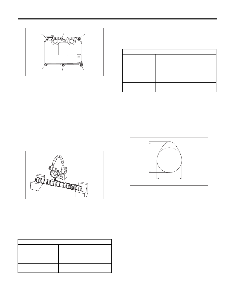
LH side
(3) Connect the PCV hose.
14) Install the high tension cord.
15) Install the timing belt cover. <Ref. to
ME(H4SO)-43, INSTALLATION, Timing Belt Cov-
er.>
16) Install the crank pulley. <Ref. to ME(H4SO)-41,
INSTALLATION, Crank Pulley.>
17) Install the V-belts. <Ref. to ME(H4SO)-39, IN-
STALLATION, V-belt.>
C: INSPECTION
1) Measure the bend, and repair or replace if nec-
essary.
Service limit:
0.025 mm (0.00098 in) or less
2) Check the journal for damage and wear. Re-
place if faulty.
3) Measure the outer diameter of camshaft journal
and inner diameter of cylinder head journal, and
check the difference (oil clearance) between the
two values. If the oil clearance is not within the
standard, replace the camshaft or cylinder head as
necessary.
4) Check the cam face condition, and remove the
minor faults by grinding with oil stone. Measure the
cam height H. If it exceeds the standard or offset
wear occurs, replace it.
Cam height H:
Cam base circle diameter A:
Intake
34.00 mm (1.3386 in)
Exhaust
34.00 mm (1.3386 in)
Base circle step of adjacent intake cams (low
speed and high speed):
0.03 mm (0.001 in) or less
5) Measure the thrust clearance of camshaft with
setting the dial gauge at end of camshaft. If the
thrust clearance is not within the standard or there
is offset wear, replace the camshaft caps and cylin-
der head as a set. If necessary, replace the cam-
shaft.
Standard:
0.030 — 0.090 mm (0.0012 — 0.0035 in)
Unit: mm (in)
Oil clearance
Standard
0.055 — 0.090
(0.0022 — 0.0035)
Camshaft journal O.D.
31.928 — 31.945
(1.2570 — 1.2577)
Journal hole I.D.
32.000 — 32.018
(1.2598 — 1.2605)
ME-02716
(a)
(b)
(c)
(d)
(e)
(f)
ME-00275
Unit: mm (in)
Intake
Constant
Standard
40.075 — 40.175
(1.5778 — 1.5817)
Low speed
Standard
35.496 — 35.596
(1.3975 — 1.4014)
High speed
Standard
40.315 — 40.415
(1.5872 — 1.5911)
Exhaust
Standard
39.289 — 39.389
(1.5468 — 1.5507)
ME-00276
H
A
ME(H4SO)-58
Cylinder Head
MECHANICAL
20.Cylinder Head
A: REMOVAL
NOTE:
• When replacing the single part, perform the work
with the engine installed to body. Refer to “Valve
Clearance” for preparation procedures. <Ref. to
ME(H4SO)-27, Valve Clearance.>
• When performing the work with the engine in-
stalled to body, the following parts must also be re-
moved/installed.
• Front exhaust pipe <Ref. to EX(H4SO)-4, RE-
MOVAL, Front Exhaust Pipe.> <Ref. to
EX(H4SO)-5, INSTALLATION, Front Exhaust
Pipe.>
1) Remove the V-belts. <Ref. to ME(H4SO)-38,
REMOVAL, V-belt.>
2) Remove the intake manifold. <Ref. to
FU(H4SO)-13, REMOVAL, Intake Manifold.>
3) Remove the crank pulley. <Ref. to ME(H4SO)-
41, REMOVAL, Crank Pulley.>
4) Remove the timing belt cover. <Ref. to
ME(H4SO)-43, REMOVAL, Timing Belt Cover.>
5) Remove the timing belt. <Ref. to ME(H4SO)-44,
REMOVAL, Timing Belt.>
6) Remove the cam sprocket. <Ref. to ME(H4SO)-
49, REMOVAL, Cam Sprocket.>
7) Remove the bolt which installs the A/C compres-
sor bracket on cylinder head.
8) Remove the valve rocker assembly. <Ref. to
ME(H4SO)-51, REMOVAL, Valve Rocker Assem-
bly.>
9) Remove the camshaft. <Ref. to ME(H4SO)-54,
REMOVAL, Camshaft.>
10) Remove the oil level gauge guide. (LH side)
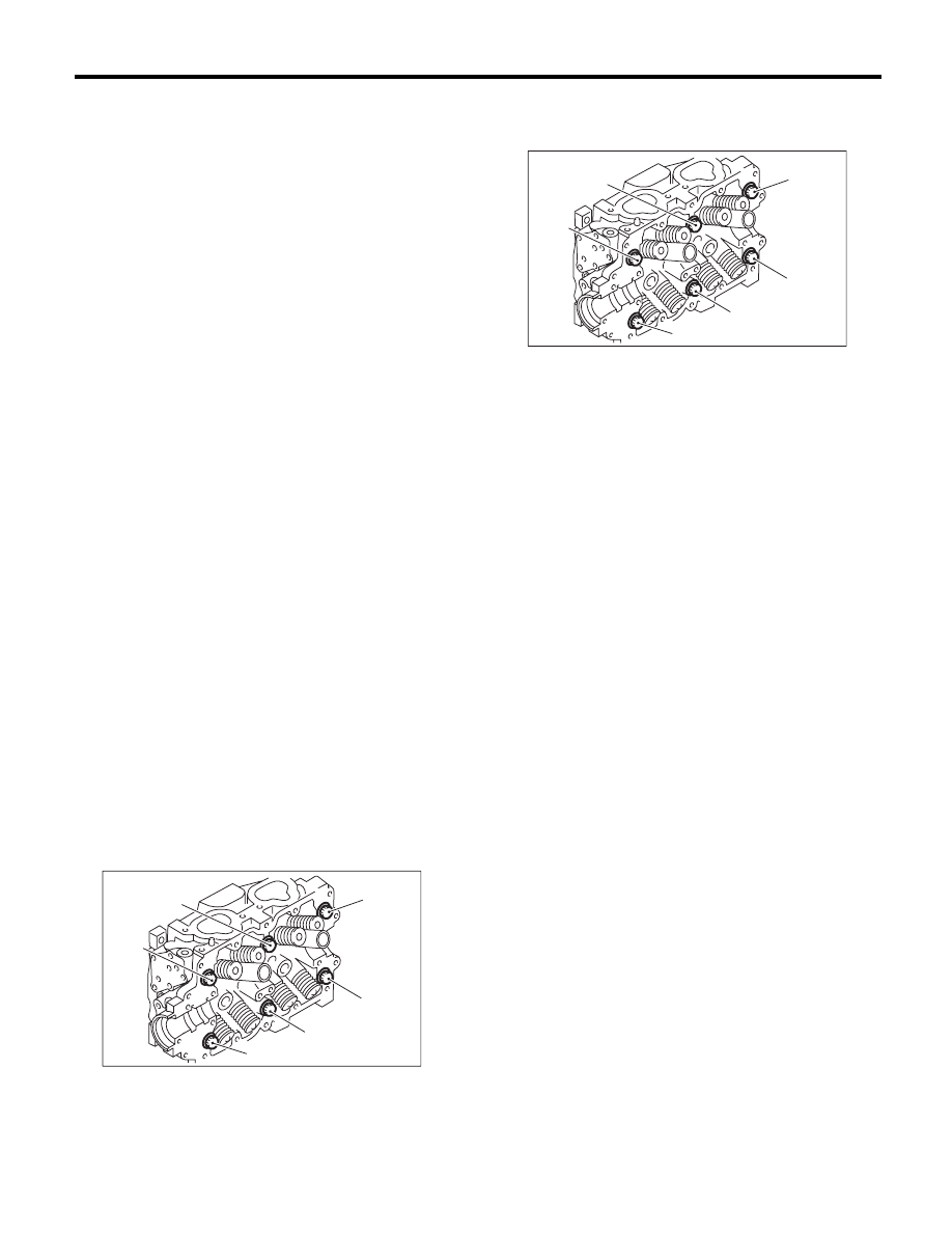
11) Remove the cylinder head bolts in alphabetical
sequence as shown in the figure.
NOTE:
Leave bolts (a) and (c) engaged by three or four
threads to prevent the cylinder head from falling.
12) While tapping the cylinder head with a plastic
hammer, separate it from cylinder block. Remove
the bolts (a) and (c) to remove cylinder head.
13) Remove the cylinder head gasket.
CAUTION:
Be careful not to scratch the mating surface of
cylinder head and cylinder block.
14) Similarly, remove the right side cylinder head.
ME-02745
( c )
( b )
( f )
( d )
( a )
( e )
ME-02745
( c )
( b )
( f )
( d )
( a )
( e )
ME(H4SO)-59
Cylinder Head
MECHANICAL
B: INSTALLATION
1) Install the cylinder head and gaskets on cylinder
block.
CAUTION:
Be careful not to scratch the mating surface of
cylinder block and cylinder head.
NOTE:
Use a new cylinder head gasket.
2) Tighten the cylinder head bolts.
(1) Apply a thin coat of engine oil to washer and
bolt thread.
(2) Tighten all bolts to 29 N·m (3.0 kgf-m, 21.4
ft-lb) in alphabetical order.
(3) Tighten all bolts to 69 N·m (7.0 kgf-m, 50.9
ft-lb) in alphabetical order.
(4) Loosen all the bolts by 180° in the reverse
order of installing, and loosen them further by
180°.
(5) Tighten all bolts to 42 N·m (4.3 kgf-m, 31.0
ft-lb) in alphabetical order.
(6) Tighten all bolts by 80 to 90° in alphabetical
order.
(7) Tighten all bolts by 40 to 45° in alphabetical
order.
CAUTION:
The tightening angle of the bolt should not ex-
ceed 45°.
(8) Further tighten the bolts (a) and (b) by 40 —
45°.
CAUTION:
Make sure the total “re-tightening angle” of the
step (7) and (8) does not exceed 90°.
3) Install the oil level gauge guide. (LH side)
Tightening torque:
6.4 N·m (0.7 kgf-m, 4.7 ft-lb)
4) Install the camshaft. <Ref. to ME(H4SO)-55, IN-
STALLATION, Camshaft.>
5) Install the valve rocker assembly. <Ref. to
ME(H4SO)-52, INSTALLATION, Valve Rocker As-
sembly.>
6) Install the A/C compressor bracket on cylinder
head.
Tightening torque:
36 N·m (3.7 kgf-m, 26.6 ft-lb)
7) Install the cam sprocket. <Ref. to ME(H4SO)-49,
INSTALLATION, Cam Sprocket.>
8) Install the timing belt. <Ref. to ME(H4SO)-45,
INSTALLATION, Timing Belt.>
9) Adjust the valve clearance. <Ref. to ME(H4SO)-
28, ADJUSTMENT, Valve Clearance.>
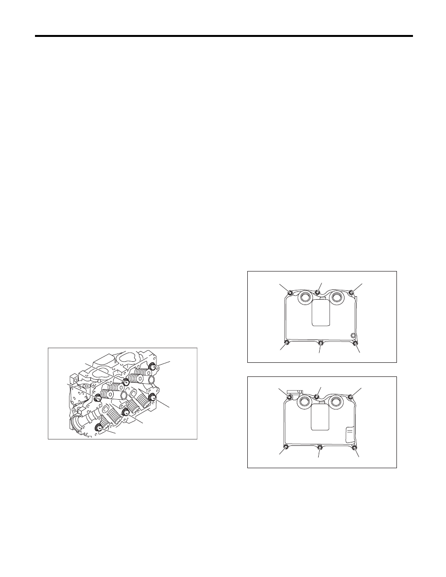
10) Install the rocker cover.
(1) Install the rocker cover gasket to the rocker
cover.
NOTE:
Use a new rocker cover gasket.
(2) Temporarily tighten the bolts in alphabetical
order shown in the figure, tighten them in two
stages.
Tightening torque:
1st
6.4 N·m (0.7 kgf-m, 4.7 ft-lb)
2nd (only (a) and (b) are tightened)
6.4 N·m (0.7 kgf-m, 4.7 ft-lb)
RH side
LH side
11) Install the timing belt cover. <Ref. to ME(H4SO)-
43, INSTALLATION, Timing Belt Cover.>
12) Install the crank pulley. <Ref. to ME(H4SO)-41,
INSTALLATION, Crank Pulley.>
13) Install the intake manifold. <Ref. to FU(H4SO)-
15, INSTALLATION, Intake Manifold.>
14) Install the V-belts. <Ref. to ME(H4SO)-39, IN-
STALLATION, V-belt.>
ME-02746
( c )
( b )
( f )
( d )
( a )
( e )
ME-02715
(a)
(b)
(c)
(d)
(e)
(f)
ME-02716
(a)
(b)
(c)
(d)
(e)
(f)
Нет комментариевНе стесняйтесь поделиться с нами вашим ценным мнением.
Текст