Subaru Legacy IV (2008 year). Service manual — part 853
WT-11
“T-type” Tire
WHEEL AND TIRE SYSTEM
6. “T-type” Tire
A: NOTE
“T-type” tire for temporary use is equipped as a
spare tire.
CAUTION:
• Do not drive at a speed greater than 80 km/h
(50 MPH).
• For the model with tire pressure monitoring
system, the indicator light may blink when run-
ning with the “T-type” tire.
B: REPLACEMENT
Refer to “Steel Wheels” for removal and installation
procedures of the “T-type” tire. <Ref. to WT-6, RE-
MOVAL, Steel Wheel.>
CAUTION:
The “T-type” tire is only for temporary use. Re-
place with a conventional tire as soon as possi-
ble.
C: INSPECTION
1) Check the tire air pressure.
Specifications:
420 kPa (4.2 kg/cm
2
, 60 psi)
2) Take stones, glass, nails, etc. out of the tread
groove.
3) Check the tires for deformation, cracks, partial
wear, or wear.
CAUTION:
Replace the tire with a new part if defective.
WT-12
Tire Pressure Monitoring System
WHEEL AND TIRE SYSTEM
7. Tire Pressure Monitoring
System
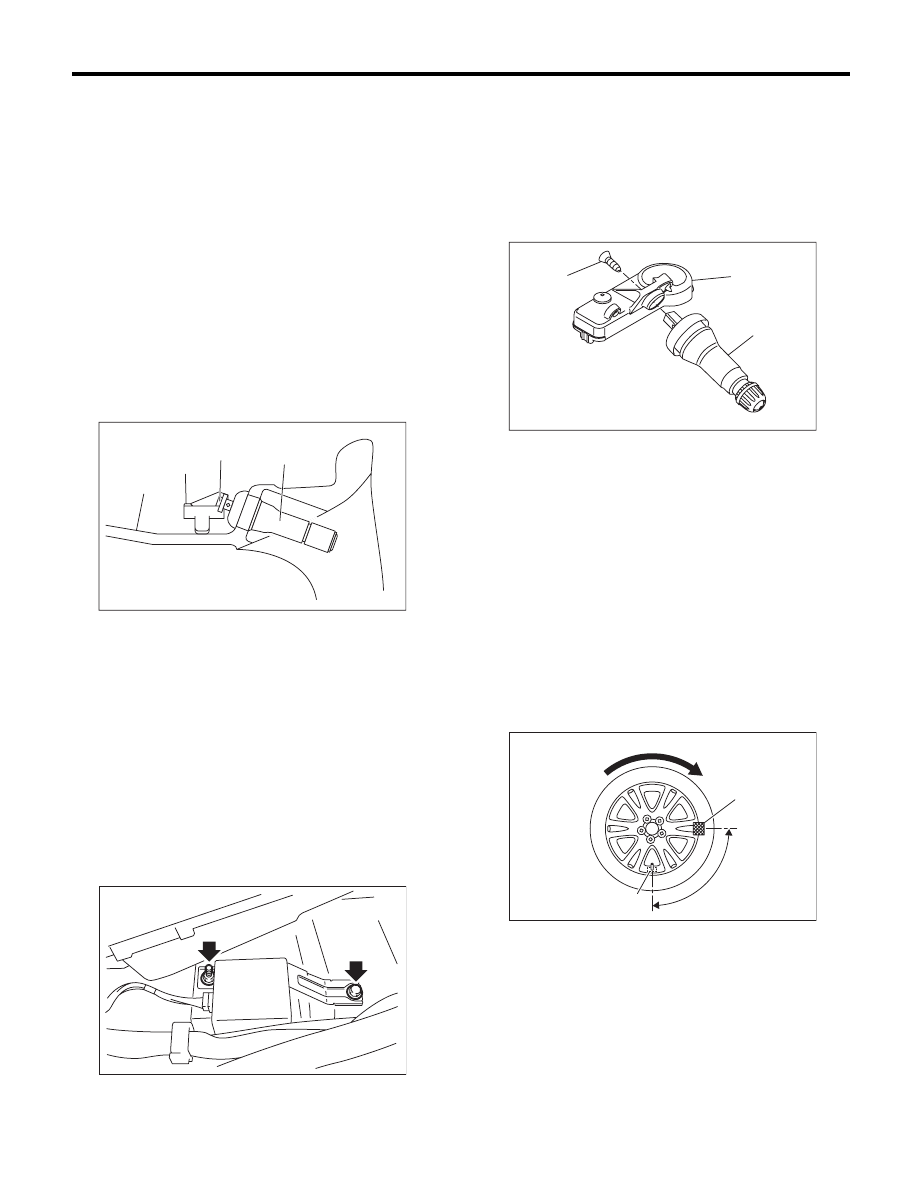
A: REMOVAL
1. TRANSMITTER (SNAP IN TYPE)
1) Remove the wheels from the vehicle. <Ref. to
WT-6, REMOVAL, Steel Wheel.>
2) Remove the tires from wheels.
CAUTION:
Use a tire changer when removing the tire from
the wheel.
3) Loosen the screw to remove the transmitter from
the valve.
NOTE:
Replace the valve and screw with a new part when
reusing transmitter.
4) Remove the valve stems from the wheel.
2. TIRE PRESSURE MONITORING
CONTROL MODULE
1) Remove the driver’s seat. <Ref. to SE-9, RE-
MOVAL, Front Seat.>
2) Turn up the floor mat in the driver’s seat area.
3) Remove the connector to remove tire pressure
monitoring control module.
B: INSTALLATION
1. TRANSMITTER (SNAP IN TYPE)
CAUTION:
Use the new transmitter assembly or replace
the new valve and screw, when installing.
1) Replace the valve and screw with a new part
when reusing transmitter.
Tightening torque:
1.4 N·m (0.1 kgf-m, 1 ft-lb)
2) Install the transmitter to the wheel by aligning it
with valve hole.
3) Install the tires to wheels.
CAUTION:
• Use a tire changer when installing tire to
wheel.
• To prevent damaging the transmitter, set the
tire changer boom in the position as shown in
the figure.
4) Install the wheels to vehicle. <Ref. to WT-6, IN-
STALLATION, Steel Wheel.>
(1) Wheel
(2) Transmitter
(3) Screw
(4) Valve
WT-00125
(1)
(2)
(4)
(3)
WT-00073
(1) Screw
(2) Transmitter
(3) Valve
(1) Transmitter
(2) Direction of turn table rotation
(3) 90°
(4) Tire changer boom
WT-00126
(2)
(3)
(1)
(1)
WT-00071
(3)
(4)
(2)
WT-13
Tire Pressure Monitoring System
WHEEL AND TIRE SYSTEM
5) Register the transmitter ID to the tire pressure
monitoring control module. <Ref. to TPM(diag)-10,
REGISTER TRANSMITTER ID, OPERATION,
Subaru Select Monitor.>
2. TIRE PRESSURE MONITORING
CONTROL MODULE
Install in the reverse order of removal.
Tightening torque:
8 N·m (0.8 kgf-m, 5.8 ft-lb)
C: ADJUSTMENT
Re-register the transmitter ID when transmitter has
been replaced or tires have been rotated. <Ref. to
TPM(diag)-10, REGISTER TRANSMITTER ID,
OPERATION, Subaru Select Monitor.>
WT-14
General Diagnostic Table
WHEEL AND TIRE SYSTEM
8. General Diagnostic Table
A: INSPECTION
Symptom
Possible cause
Corrective action
Wheel is out of balance.
Improperly inflated tire
Adjust the tire pressure.
Uneven wear
Check the tire referring to Abnormal tire wear in this table, carry out
the procedure and replace the tire.
Front wheel alignment
Check the front wheel alignment. <Ref. to FS-6, INSPECTION, Wheel
Alignment.>
Rear wheel alignment
Check the rear wheel alignment. <Ref. to RS-7, INSPECTION, Wheel
Alignment.>
Front strut
Check the front strut. <Ref. to FS-23, INSPECTION, Front Strut.>
Rear shock absorber
Check the rear shock absorber. <Ref. to RS-16, INSPECTION, Rear
Shock Absorber.>
Front axle
Check the front axle. <Ref. to DS-16, INSPECTION, Front Axle.>
Front hub unit bearing
Check the front hub unit bearing. <Ref. to DS-18, INSPECTION, Front
Hub Unit Bearing.>
Rear hub unit bearing
Check the rear hub unit bearing. <Ref. to DS-21, INSPECTION, Rear
Hub Unit Bearing.>
Vehicle is abnormally out of
balance.
Improperly inflated tire
Adjust the tire pressure.
Uneven wear
Check the tire referring to Abnormal tire wear in this table, carry out
the procedure and replace the tire.
Front stabilizer
Inspect the front stabilizer. <Ref. to FS-15, INSPECTION, Front Stabi-
lizer.>
Front wheel alignment
Check the front wheel alignment. <Ref. to FS-6, INSPECTION, Wheel
Alignment.>
Rear wheel alignment
Check the rear wheel alignment. <Ref. to RS-7, INSPECTION, Wheel
Alignment.>
Abnormal wheel vibration
Improperly inflated tire
Adjust the tire pressure.
Uneven wear
Check the tire referring to Abnormal tire wear in this table, carry out
the procedure and replace the tire.
Improper wheel balancing
Check the wheel balance. <Ref. to WT-8, ADJUSTMENT, Wheel Bal-
ancing.>
Front axle
Check the front axle. <Ref. to DS-16, INSPECTION, Front Axle.>
Front hub unit bearing
Check the front hub unit bearing. <Ref. to DS-18, INSPECTION, Front
Hub Unit Bearing.>
Rear hub unit bearing
Check the rear hub unit bearing. <Ref. to DS-21, INSPECTION, Rear
Hub Unit Bearing.>
Abnormal tire wear
Improperly inflated tire
Adjust the tire pressure.
Improper wheel balancing
Check the wheel balance. <Ref. to WT-8, ADJUSTMENT, Wheel Bal-
ancing.>
Front wheel alignment
Check the front wheel alignment. <Ref. to FS-6, INSPECTION, Wheel
Alignment.>
Rear wheel alignment
Check the rear wheel alignment. <Ref. to RS-7, INSPECTION, Wheel
Alignment.>
Нет комментариевНе стесняйтесь поделиться с нами вашим ценным мнением.
Текст