Subaru Legacy IV (2008 year). Service manual — part 757
5AT(diag)-43
Diagnostic Procedure with Diagnostic Trouble Code (DTC)
AUTOMATIC TRANSMISSION (DIAGNOSTICS)
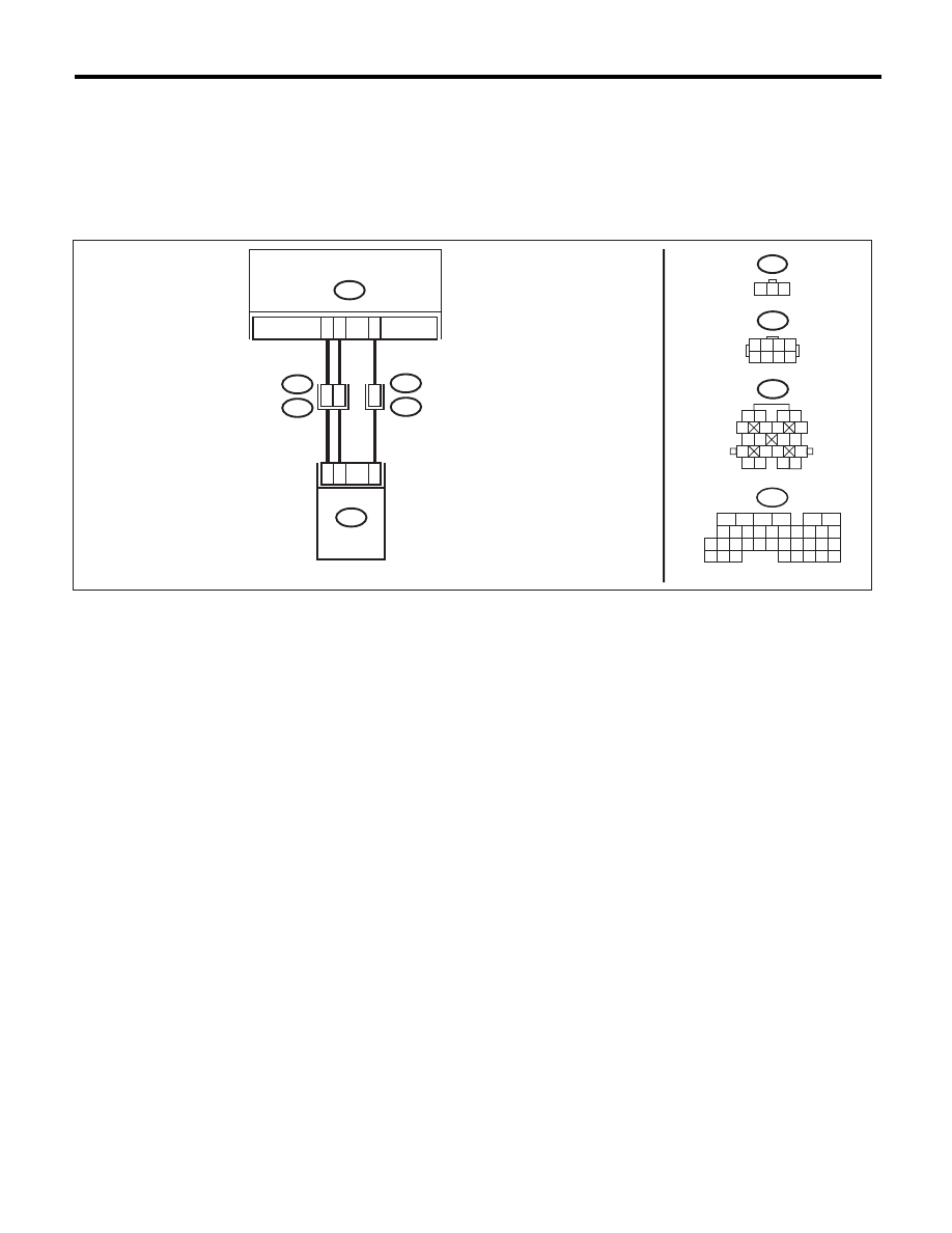
D: DTC P0715 INPUT/TURBINE SPEED SENSOR CIRCUIT
DTC DETECTING CONDITION:
Input signal circuit of TCM is open or shorted.
TROUBLE SYMPTOM:
• Excessive shift shock
• Does not shift to 5th.
WIRING DIAGRAM:
AT-04349
AT1
1 2 3
1 2 3 4
5 6 7 8
B11
B12
1 2
5
6 7
8
13
14 15
16
9 10
11 12
3 4
17 18
19 20
B54
26
7
B12
T3
B11
T4
TCM
16
2
27
AT1
B54
16
10 11 12 13 14 15
25
24
30
9
8
7
17 18 19 20
28
21 22 23
29
32
31
1
2
3
4
5
6
27
26
33 34 35
7
2
1
3
TURBINE SPEED SENSOR 1

5AT(diag)-44
Diagnostic Procedure with Diagnostic Trouble Code (DTC)
AUTOMATIC TRANSMISSION (DIAGNOSTICS)
Step
Check
Yes
No
1
CHECK TCM I/O SIGNAL.
Check the power supply and ground I/O signals.
<Ref. to 5AT(diag)-14, ELECTRICAL SPECIFI-
CATION, Transmission Control Module (TCM) I/
O Signal.>
Is TCM I/O signal OK?
Go to step 2.
Repair the open or
short circuit for
power supply and
ground.
2
CHECK TCM AND TRANSMISSION HAR-
NESS CONNECTOR.
1) Disconnect the connectors from TCM and
transmission.
2) Measure the resistance of harness between
TCM connector and transmission connector.
Connector & terminal
(B54) No. 16 — (B11) No. 2:
(B54) No. 26 — (B12) No. 7:
(B54) No. 27 — (B11) No. 7:
Is the resistance less than 1
:? Go to step 3.
Repair the open
circuit of harness
between TCM and
transmission con-
nector.
3
CHECK TCM AND TRANSMISSION HAR-
NESS CONNECTOR.
Measure the resistance of harness between
TCM connector and chassis ground.
Connector & terminal
(B54) No. 16 — Chassis ground:
(B54) No. 26 — Chassis ground:
(B54) No. 27 — Chassis ground:
Is the resistance less than 1 M
:? Go to step 4.
Repair the short
circuit of harness
between TCM and
transmission con-
nector.
4
CHECK TCM POWER SUPPLY OUTPUT.
1) Connect the connector to the TCM. (Trans-
mission connector is disconnected)
2) Turn the ignition switch to ON. (engine OFF)
3) Measure the voltage between transmission
connector and chassis ground.
Connector & terminal
(B11) No. 7 (+) — Chassis ground (–):
Is the voltage 10 — 13 V?
Go to step 5.
Replace the TCM.
<Ref. to 5AT-60,
Transmission Con-
trol Module
(TCM).>
5
CHECK INPUT CIRCUIT OF TCM TURBINE
SPEED SENSOR.
Measure the voltage between TCM connector
terminals.
Connector & terminal
(B12) No. 7 (+) — (B11) No. 2 (–):
Is the voltage 4 — 6 V?
Go to step 6.
Replace the TCM.
<Ref. to 5AT-60,
Transmission Con-
trol Module
(TCM).>
6
CHECK HARNESS ASSEMBLY (TURBINE
SPEED SENSOR GROUND).
Check the installing condition of ground con-
necting harness of harness assembly (used for
both of turbine speed sensor 1, rear vehicle
speed sensor).
Is the ground connecting har-
ness installed securely to the
transmission body? Is there
any serious damage in the har-
ness and terminal?
Go to step 7.
When poor instal-
lation of ground
occurs, install it
securely. Replace
the transmission
assembly if the
harness or termi-
nal is damaged.
<Ref. to 5AT-39,
Automatic Trans-
mission Assem-
bly.>

5AT(diag)-45
Diagnostic Procedure with Diagnostic Trouble Code (DTC)
AUTOMATIC TRANSMISSION (DIAGNOSTICS)
7
CHECK HARNESS ASSEMBLY.
1) Turn the ignition switch to OFF.
2) Disconnect the connector from transmis-
sion.
3) Disconnect the connector from turbine
speed sensor 1.
4) Measure the resistance between transmis-
sion connector and turbine speed sensor 1 con-
nector.
Connector & terminal
(T3) No. 7 — (AT1) No. 2:
(T4) No. 7 — (AT1) No. 3:
(T4) No. 2 — (AT1) No. 1:
(AT1) No. 1 — Chassis ground:
Is the resistance less than 1
:? Go to step 8.
Repair the open
circuit of harness
between TCM and
transmission con-
nector, or poor
contact of connec-
tor.
8
CHECK HARNESS ASSEMBLY.
Measure the resistance between transmission
connector and chassis ground.
Connector & terminal
(T3) No. 7 — Chassis ground:
(T4) No. 7 — Chassis ground:
(T4) No. 2 — Chassis ground:
Is the resistance 1 M
: or
more?
Go to step 9.
Repair the short
circuit of harness
between TCM and
transmission con-
nector.
9
CHECK INPUT SIGNAL FOR TCM USING
SUBARU SELECT MONITOR.
1) Connect all connectors.
2) Lift up the vehicle.
NOTE:
Raise all wheels off the floor.
3) Start the engine, and set the vehicle in 4th
speed driving condition of manual mode.
NOTE:
Turbine speed sensor 1 signal can be mea-
sured only on 4th speed.
4) Read the current data of turbine speed sen-
sor 1 using the Subaru Select Monitor. <Ref. to
5AT(diag)-18, READ CURRENT DATA, OPER-
ATION, Subaru Select Monitor.>
NOTE:
The speed difference between front and rear
wheels may illuminate the ABS warning light,
but this does not indicate a malfunction. When
AT control diagnosis is finished, perform the
ABS or VDC clear memory of on-board diag-
nostics system. <Ref. to ABS(diag)-20, Clear
Memory Mode.> <Ref. to VDC(diag)-23, Clear
Memory Mode.>
Does the value of the turbine
speed sensor 1 change
depending on the acceleration,
deceleration and shifting range
of the vehicle?
Even if the AT OIL
TEMP light blinks,
the system is in
normal condition.
A temporary poor
contact of connec-
tor or harness may
be the cause.
Repair the poor
contact of harness
between ATF tem-
perature sensor
and transmission
connector.
Replace the tur-
bine speed sensor
1. <Ref. to 5AT-56,
Turbine Speed
Sensor 1.>
Step
Check
Yes
No
5AT(diag)-46
Diagnostic Procedure with Diagnostic Trouble Code (DTC)
AUTOMATIC TRANSMISSION (DIAGNOSTICS)
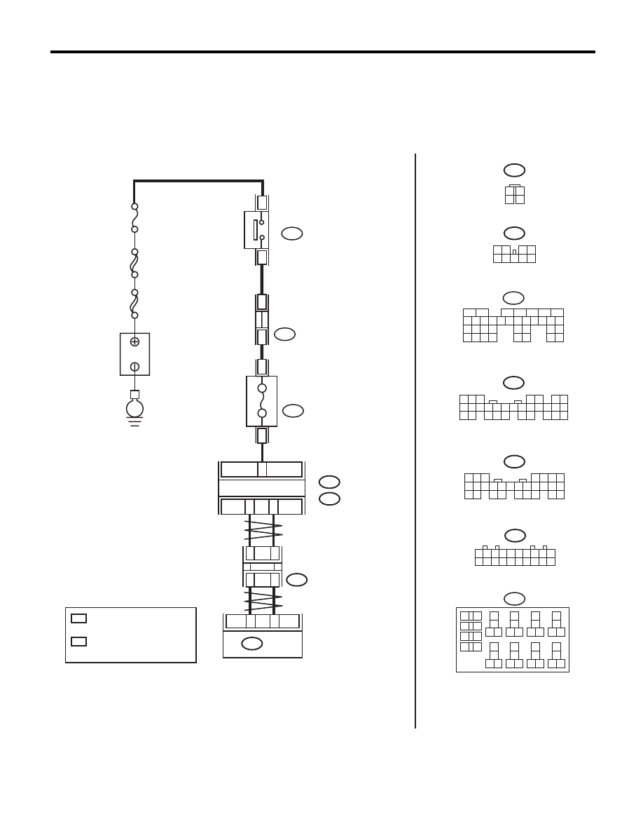
E: DTC P0719 BRAKE SWITCH CIRCUIT LOW
DTC DETECTING CONDITION:
Stop light switch malfunction, open input signal circuit
TROUBLE SYMPTOM:
Brake down control does not operate at S# mode.
WIRING DIAGRAM:
B280
B:
B281
C:
C23
B20
B30
B159
2
1
3 4
8 9
7
6
5
B280
8
7
6
5
4
3
2
1
22
23
21
20
19
16
15
14
13
12
11
10
9
17
30
18
29
28
27
26
25
24
B281
8
7
6
5
4
3
2
1
21
22
20
19
16
15
14
13
12
11
10
9
17 18
28
27
26
25
24
23
21
20
B55
C:
B:
B65
1
2
3
4
TCM
9
5
B65
B225
7.5A
4
3
AT-04350
B55
5
6
7
2
1
3
4
29
10 11 12 13 14 15
25
24
16
30
9
8
17 18 19
20
28
21 22 23
32
31
26 27
33
34 35
1 2 3 4 5 6 7 8 9 10
11 12 13 14 15 16 17 18 19 20
B365
B365
1
*
2
*
1
*
2
*
SBF-2
E
FUSE
(RELAY BLOCK)
3
2
B225
13
14
15 16
17
27
24
25
26
20
21
22
23
29
30
31
28
32
35
33
34
37
38
39
36
40
8
9
10
11 12
1
2
5
3
4
7
6
19
18
RELAY BLOCK
BODY INTEGRATED UNIT
FUSE & RELAY
BOX (F/B)
B159
STOP LIGHT
SWITCH
B
A
TTER
Y
MAIN SBF
No.8
:
:
1
*
2
*
TERMINAL No. OPTIONAL
ARRANGEMENT
AMONG 1, 2 ,3,11,12 AND 13
TERMINAL No. OPTIONAL
ARRANGEMENT
AMONG 8, 9, 10, 18, 19 AND 20
CAN
JOINT
CONNECTOR
Нет комментариевНе стесняйтесь поделиться с нами вашим ценным мнением.
Текст