Subaru Legacy IV (2008 year). Service manual — part 142

EN(H4SO)(diag)-171
Diagnostic Procedure with Diagnostic Trouble Code (DTC)
ENGINE (DIAGNOSTICS)
Step
Check
Yes
No
1
CHECK HARNESS BETWEEN ECM AND
ELECTRONIC THROTTLE CONTROL.
1) Turn the ignition switch to OFF.
2) Disconnect the connectors from ECM and
electronic throttle control.
3) Measure the resistance between ECM and
chassis ground.
Connector & terminal
(B134) No. 19 — Chassis ground:
(B134) No. 28 — Chassis ground:
Is the resistance 1 M
: or
more?
Go to step 2.
Repair the short
circuit to ground in
harness between
ECM and elec-
tronic throttle con-
trol connector.
2
CHECK SHORT CIRCUIT INSIDE THE ECM.
1) Connect the connector to ECM.
2) Measure the resistance between electronic
throttle control connector and engine ground.
Connector & terminal
(E57) No. 4 — Engine ground:
Is the resistance 1 M
: or
more?
Replace the elec-
tronic throttle con-
trol. <Ref. to
FU(H4SO)-12,
Throttle Body.>
Repair the short
circuit to ground in
harness between
ECM and elec-
tronic throttle con-
trol connector.
Replace the ECM if
defective. <Ref. to
FU(H4SO)-39,
Engine Control
Module (ECM).>
EN(H4SO)(diag)-172
Diagnostic Procedure with Diagnostic Trouble Code (DTC)
ENGINE (DIAGNOSTICS)
AS:DTC P0223 THROTTLE/PEDAL POSITION SENSOR/SWITCH “B” CIRCUIT
HIGH
DTC DETECTING CONDITION:
• Immediately at fault recognition
• GENERAL DESCRIPTION <Ref. to GD(H4SO)-78, DTC P0223 THROTTLE/PEDAL POSITION SEN-
SOR/SWITCH “B” CIRCUIT HIGH, Diagnostic Trouble Code (DTC) Detecting Criteria.>
TROUBLE SYMPTOM:
• Improper idling
• Poor driving performance
• Engine stalls.
CAUTION:
After repair or replacement of faulty parts, perform Clear Memory Mode <Ref. to EN(H4SO)(diag)-50,
OPERATION, Clear Memory Mode.>, and Inspection Mode <Ref. to EN(H4SO)(diag)-41, PROCEDURE,
Inspection Mode.>.
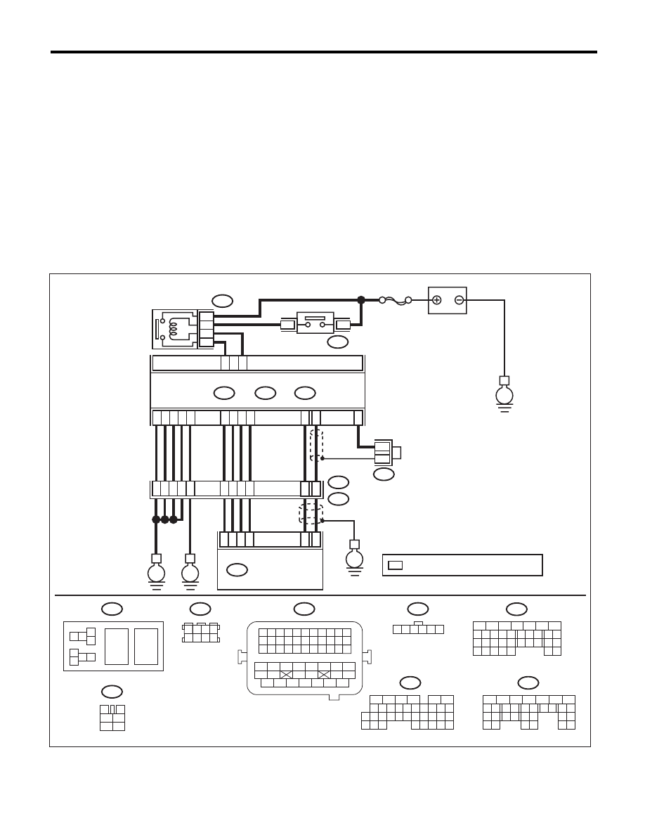
WIRING DIAGRAM:
EN-06838
SBF-7
B134
A:
B137
B136
D:
B362
C:
E
C1
C21
D4
D5
A29
A19
D3
D7
D1
D2
A5
A28
A18
C6
ECM
5
8
7
6
B362
B47
B21
E57
B122
1 2
7 8
3
4
5
6
1 2 3 4 5 6 7 8 9 10 11
12 13 14 15 16 17 18 19 20 21 22
23 24 25
34 35
36 37 38 39 40 41
48 49
50 51 52 53 54
42 43
44 45
46 47
26 27 28 29 30 31 32 33
1 2 3 4
5 6 7 8
1
2
7
8 9
5
6
3
4
10 11 12
19 20 21
29
30 31
13 14 15 16 17
27
28
18
22 23
24 25
26
1
2
8 9
5
6
3
4
10 11 12
19 20 21
29 30
31
13 14 15 16
17
27
28
18
22 23 24 25 26
7
32 33 34 35
B134
A:
B136
C:
B137
D:
BATTERY
ELECTRONIC
THROTTLE
CONTROL RELAY
MAIN RELAY
1 2 3 4 5 6
E2
B21
B122
E
E
E
39
20
E57
4
6
1
2
3
5
34
35
36
37
52
*
*
ELECTRONIC
THROTTLE CONTROL
: TERMINAL No. OPTIONAL ARRANGEMENT
*
18
17
38
19
8
5
6
10 11 12 13 14 15
7
2
1
3
4
16
30
19 20
22
28 29
9
17
18
25
21
23 24
32
31
26 27
33 34
3
4
1
2
5
6
6
4
B47

EN(H4SO)(diag)-173
Diagnostic Procedure with Diagnostic Trouble Code (DTC)
ENGINE (DIAGNOSTICS)
AT:DTC P0301 CYLINDER 1 MISFIRE DETECTED
NOTE:
For the diagnostic procedure, refer to DTC P0304. <Ref. to EN(H4SO)(diag)-174, DTC P0304 CYLINDER 4
MISFIRE DETECTED, Diagnostic Procedure with Diagnostic Trouble Code (DTC).>
AU:DTC P0302 CYLINDER 2 MISFIRE DETECTED
NOTE:
For the diagnostic procedure, refer to DTC P0304. <Ref. to EN(H4SO)(diag)-174, DTC P0304 CYLINDER 4
MISFIRE DETECTED, Diagnostic Procedure with Diagnostic Trouble Code (DTC).>
AV:DTC P0303 CYLINDER 3 MISFIRE DETECTED
NOTE:
For the diagnostic procedure, refer to DTC P0304. <Ref. to EN(H4SO)(diag)-174, DTC P0304 CYLINDER 4
MISFIRE DETECTED, Diagnostic Procedure with Diagnostic Trouble Code (DTC).>
Step
Check
Yes
No
1
CHECK HARNESS BETWEEN ECM AND
ELECTRONIC THROTTLE CONTROL.
1) Turn the ignition switch to OFF.
2) Disconnect the connectors from ECM and
electronic throttle control.
3) Measure the resistance of harness between
ECM and electronic throttle control connector.
Connector & terminal
(B134) No. 28 — (E57) No. 4:
(B134) No. 29 — (E57) No. 3:
Is the resistance less than 1
:? Go to step 2.
Repair the harness
and connector.
NOTE:
In this case, repair
the following item:
• Open circuit in
harness between
ECM and electron-
ic throttle control
connector
• Poor contact of
coupling connector
2
CHECK HARNESS BETWEEN ECM AND
ELECTRONIC THROTTLE CONTROL.
1) Connect the connector to ECM.
2) Measure the resistance between electronic
throttle control connector and engine ground.
Connector & terminal
(E57) No. 3 — Engine ground:
Is the resistance less than 5
:? Go to step 3.
Repair the harness
and connector.
NOTE:
In this case, repair
the following item:
• Open circuit of
harness between
ECM and engine
ground
• Poor contact in
ECM connector
• Poor contact of
coupling connector
3
CHECK HARNESS BETWEEN ECM AND
ELECTRONIC THROTTLE CONTROL.
1) Turn the ignition switch to ON.
2) Measure the voltage between electronic
throttle control connector and engine ground.
Connector & terminal
(E57) No. 4 (+) — Engine ground (–):
Is the voltage 4.85 V or more?
Repair the short
circuit to power in
the harness
between ECM and
electronic throttle
control connector.
Go to step 4.
4
CHECK HARNESS BETWEEN ECM AND
ELECTRONIC THROTTLE CONTROL.
1) Turn the ignition switch to OFF.
2) Disconnect the connectors from ECM.
3) Measure the resistance between ECM con-
nectors.
Connector & terminal
(B134) No. 19 — (B134) No. 28:
Is the resistance 1 M
: or
more?
Repair poor con-
tact of the elec-
tronic throttle
control connector.
Replace the elec-
tronic throttle con-
trol if defective.
<Ref. to
FU(H4SO)-12,
Throttle Body.>
Repair the short
circuit to power in
the harness
between ECM and
electronic throttle
control connector.
EN(H4SO)(diag)-174
Diagnostic Procedure with Diagnostic Trouble Code (DTC)
ENGINE (DIAGNOSTICS)
AW:DTC P0304 CYLINDER 4 MISFIRE DETECTED
DTC DETECTING CONDITION:
• Two consecutive driving cycles with fault
• Immediately at fault recognition (A misfire which could damage catalyst occurs.)
• GENERAL DESCRIPTION <Ref. to GD(H4SO)-85, DTC P0304 CYLINDER 4 MISFIRE DETECTED, Di-
agnostic Trouble Code (DTC) Detecting Criteria.>
TROUBLE SYMPTOM:
• Engine stalls.
• Improper idling
• Rough driving
CAUTION:
After repair or replacement of faulty parts, perform Clear Memory Mode <Ref. to EN(H4SO)(diag)-50,
OPERATION, Clear Memory Mode.>, and Inspection Mode <Ref. to EN(H4SO)(diag)-41, PROCEDURE,
Inspection Mode.>.
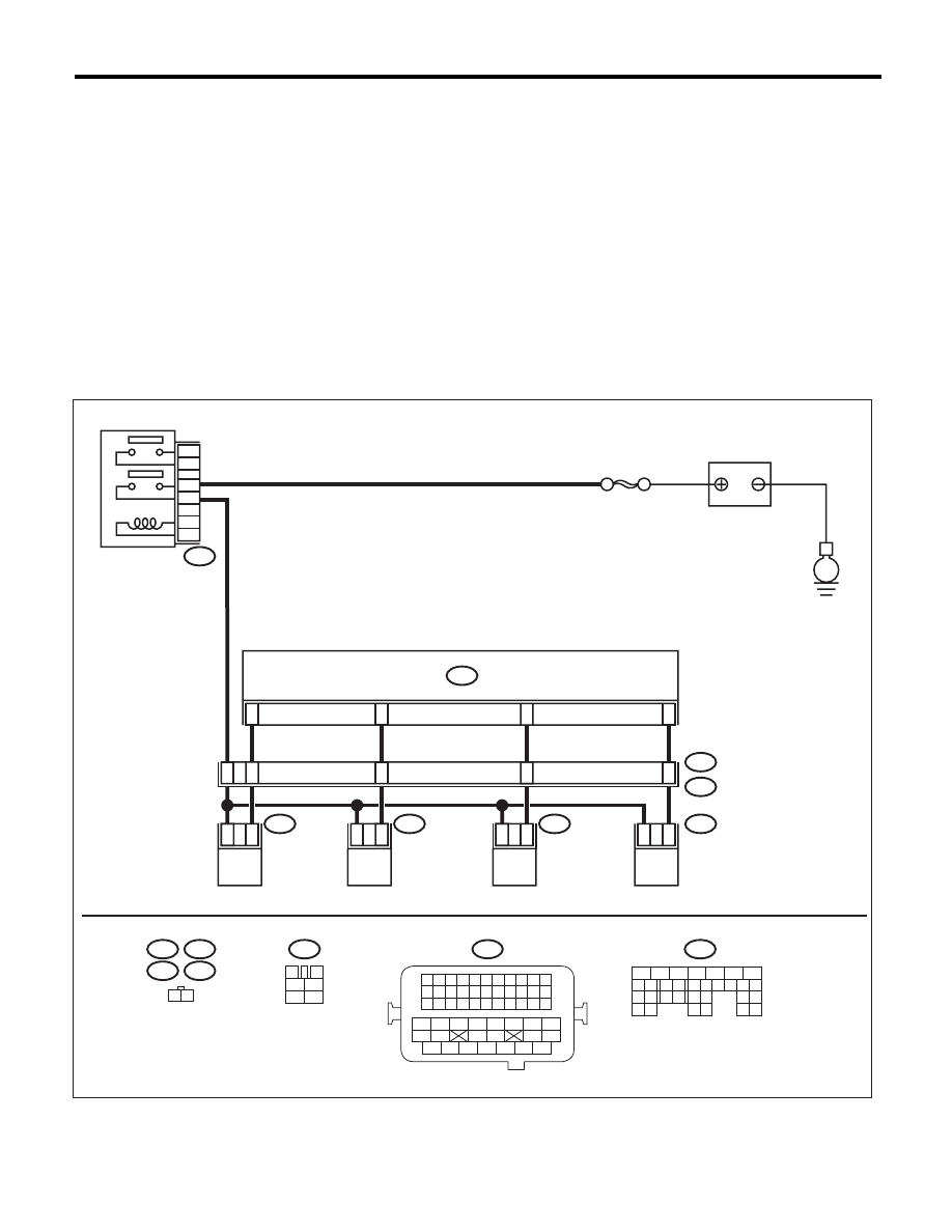
WIRING DIAGRAM:
EN-06833
E6
E17
E5
E16
1 2
1
2
1
2
1
2
1
2
10
9
8
11
42
48
43
44
45
B137
E5
E16
E6
E17
B21
E2
SBF-7
B47
1
2
4
6
3
5
B47
3
4
1
2
5
6
E
B137
B21
1 2 3 4
12 13 14 15
5 6 7 8
16 17 18 19
9 10 11
20 21 22
23 24 25 26 27 28 29 30 31 32 33
35
34
37
36
39
38
41
40
43
42
44
45
47
46
49
48
51
50
53
52
54
ECM
FUEL INJECTOR
No. 1
MAIN RELAY
BATTERY
FUEL INJECTOR
No. 2
FUEL INJECTOR
No. 3
FUEL INJECTOR
No. 4
5
6
7
8
2
1
9
4
3
10
22 23
11 12 13 14 15
24 25
26
16 17
18 19 20 21
27
28 29
30 31
Нет комментариевНе стесняйтесь поделиться с нами вашим ценным мнением.
Текст