Subaru Legacy IV (2008 year). Service manual — part 141

EN(H4SO)(diag)-167
Diagnostic Procedure with Diagnostic Trouble Code (DTC)
ENGINE (DIAGNOSTICS)
Step
Check
Yes
No
1
CHECK CURRENT DATA.
1) Start the engine.
2) Read the data of oil temperature sensor sig-
nal using Subaru Select Monitor or general
scan tool.
NOTE:
• SUBARU SELECT MONITOR
For detailed operation procedure, refer to
“READ CURRENT DATA FOR ENGINE”. <Ref.
to EN(H4SO)(diag)-33, Subaru Select Moni-
tor.>
• General Scan Tool
For detailed operation procedures, refer to the
general scan tool operation manual.
Is the oil temperature 215°C
(419°F) or more?
Go to step 2.
Even if DTC is
detected, the cir-
cuit has returned to
a normal condition
at this time. Repro-
duce the failure,
and then perform
the diagnosis
again.
NOTE:
In this case, tem-
porary poor con-
tact of connector
may be the cause.
2
CHECK HARNESS BETWEEN ECM AND OIL
TEMPERATURE SENSOR CONNECTOR.
1) Turn the ignition switch to OFF.
2) Disconnect the connector from ECM and oil
temperature sensor.
3) Measure the resistance between ECM and
chassis ground.
Connector & terminal
(B134) No. 23 — Chassis ground:
Is the resistance 1 M
: or
more?
Replace the oil
temperature sen-
sor. <Ref. to
FU(H4SO)-34, Oil
Temperature Sen-
sor.>
Repair the short
circuit to ground in
harness between
ECM and oil tem-
perature sensor.
EN(H4SO)(diag)-168
Diagnostic Procedure with Diagnostic Trouble Code (DTC)
ENGINE (DIAGNOSTICS)
AQ:DTC P0198 ENGINE OIL TEMPERATURE SENSOR HIGH
DTC DETECTING CONDITION:
• Immediately at fault recognition
• GENERAL DESCRIPTION <Ref. to GD(H4SO)-76, DTC P0198 ENGINE OIL TEMPERATURE SENSOR
HIGH, Diagnostic Trouble Code (DTC) Detecting Criteria.>
TROUBLE SYMPTOM:
• Hard to start
• Improper idling
• Poor driving performance
CAUTION:
After repair or replacement of faulty parts, perform Clear Memory Mode <Ref. to EN(H4SO)(diag)-50,
OPERATION, Clear Memory Mode.>, and Inspection Mode <Ref. to EN(H4SO)(diag)-41, PROCEDURE,
Inspection Mode.>.
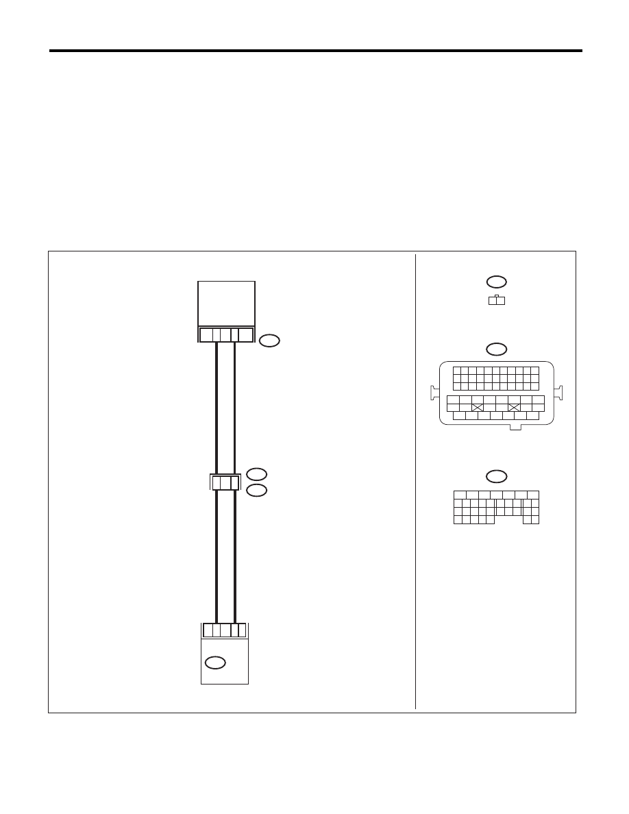
WIRING DIAGRAM:
EN-04036
E75
E2
B21
B134
ECM
1
29
2
23
E75
1 2
B21
1 2 3 4
12 13 14 15
5 6 7 8
16 17 18 19
9 10 11
20 21 22
23 24 25 26 27 28 29 30 31 32 33
35
34
37
36
39
38
41
40
43
42
44
45
47
46
49
48
51
50
53
52
54
B134
OIL
TEMPERATURE
SENSOR
19
6
5
6
7
8
2
1
9
4
3
10
24
22 23
25
11 12 13 14 15
26 27
28
16 17
18 19 20 21
33 34
29
32
30 31

EN(H4SO)(diag)-169
Diagnostic Procedure with Diagnostic Trouble Code (DTC)
ENGINE (DIAGNOSTICS)
Step
Check
Yes
No
1
CHECK CURRENT DATA.
1) Start the engine.
2) Read the data of oil temperature sensor sig-
nal using Subaru Select Monitor or general
scan tool.
NOTE:
• SUBARU SELECT MONITOR
For detailed operation procedure, refer to
“READ CURRENT DATA FOR ENGINE”. <Ref.
to EN(H4SO)(diag)-33, Subaru Select Moni-
tor.>
• General Scan Tool
For detailed operation procedures, refer to the
general scan tool operation manual.
Is the oil temperature less than
–40°C (–40°F)?
Go to step 2.
Even if DTC is
detected, the cir-
cuit has returned to
a normal condition
at this time. Repro-
duce the failure,
and then perform
the diagnosis
again.
NOTE:
In this case, tem-
porary poor con-
tact of connector
may be the cause.
2
CHECK POOR CONTACT.
Check for poor contact of ECM and oil tempera-
ture sensor connector.
Is there poor contact in ECM or
oil temperature sensor connec-
tor?
Repair the poor
contact in ECM or
oil temperature
sensor connector.
Go to step 3.
3
CHECK HARNESS BETWEEN ECM AND OIL
TEMPERATURE SENSOR CONNECTOR.
1) Turn the ignition switch to OFF.
2) Disconnect the connector from ECM and oil
temperature sensor.
3) Measure the resistance of harness between
ECM and oil temperature sensor connector.
Connector & terminal
(B134) No. 23 — (E75) No. 2:
(B134) No. 29 — (E75) No. 1:
Is the resistance less than 1
:? Go to step 4.
Repair the harness
and connector.
NOTE:
In this case, repair
the following item:
• Open circuit in
harness between
ECM and oil tem-
perature sensor
connector
• Poor contact of
coupling connector
4
CHECK HARNESS BETWEEN ECM AND OIL
TEMPERATURE SENSOR CONNECTOR.
1) Connect all connectors.
2) Turn the ignition switch to ON.
3) Measure the voltage between ECM and
chassis ground.
Connector & terminal
(B134) No. 23 (+) — Chassis ground (–):
Is the voltage 5 V or more?
Repair the short
circuit in harness
to power supply
between ECM and
oil temperature
sensor connector.
Replace the oil
temperature sen-
sor. <Ref. to
FU(H4SO)-34, Oil
Temperature Sen-
sor.>
EN(H4SO)(diag)-170
Diagnostic Procedure with Diagnostic Trouble Code (DTC)
ENGINE (DIAGNOSTICS)
AR:DTC P0222 THROTTLE/PEDAL POSITION SENSOR/SWITCH “B” CIRCUIT
LOW
DTC DETECTING CONDITION:
• Immediately at fault recognition
• GENERAL DESCRIPTION <Ref. to GD(H4SO)-77, DTC P0222 THROTTLE/PEDAL POSITION SEN-
SOR/SWITCH “B” CIRCUIT LOW, Diagnostic Trouble Code (DTC) Detecting Criteria.>
TROUBLE SYMPTOM:
• Improper idling
• Poor driving performance
• Engine stalls.
CAUTION:
After repair or replacement of faulty parts, perform Clear Memory Mode <Ref. to EN(H4SO)(diag)-50,
OPERATION, Clear Memory Mode.>, and Inspection Mode <Ref. to EN(H4SO)(diag)-41, PROCEDURE,
Inspection Mode.>.
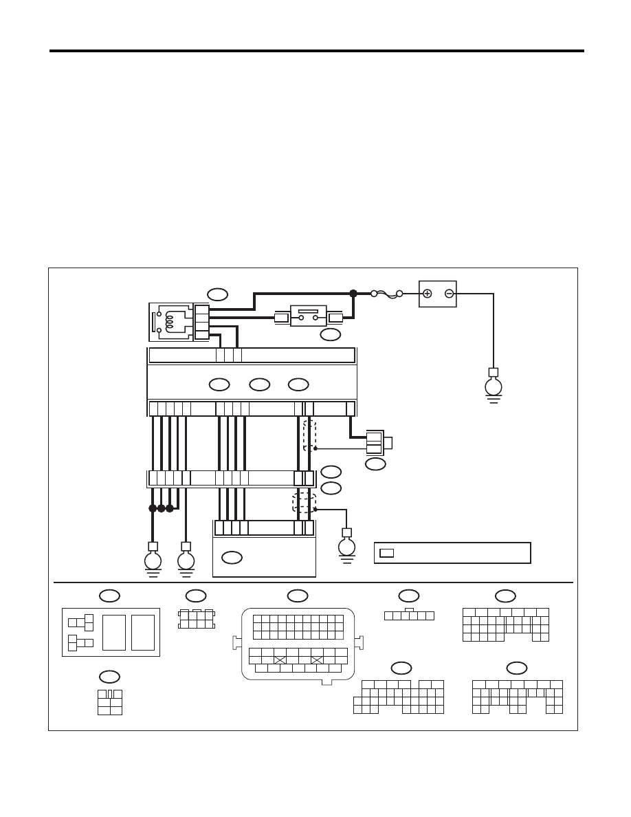
WIRING DIAGRAM:
EN-06838
SBF-7
B134
A:
B137
B136
D:
B362
C:
E
C1
C21
D4
D5
A29
A19
D3
D7
D1
D2
A5
A28
A18
C6
ECM
5
8
7
6
B362
B47
B21
E57
B122
1 2
7 8
3
4
5
6
1 2 3 4 5 6 7 8 9 10 11
12 13 14 15 16 17 18 19 20 21 22
23 24 25
34 35
36 37 38 39 40 41
48 49
50 51 52 53 54
42 43
44 45
46 47
26 27 28 29 30 31 32 33
1 2 3 4
5 6 7 8
1
2
7
8 9
5
6
3
4
10 11 12
19 20 21
29
30 31
13 14 15 16 17
27
28
18
22 23
24 25
26
1
2
8 9
5
6
3
4
10 11 12
19 20 21
29 30
31
13 14 15 16
17
27
28
18
22 23 24 25 26
7
32 33 34 35
B134
A:
B136
C:
B137
D:
BATTERY
ELECTRONIC
THROTTLE
CONTROL RELAY
MAIN RELAY
1 2 3 4 5 6
E2
B21
B122
E
E
E
39
20
E57
4
6
1
2
3
5
34
35
36
37
52
*
*
ELECTRONIC
THROTTLE CONTROL
: TERMINAL No. OPTIONAL ARRANGEMENT
*
18
17
38
19
8
5
6
10 11 12 13 14 15
7
2
1
3
4
16
30
19 20
22
28 29
9
17
18
25
21
23 24
32
31
26 27
33 34
3
4
1
2
5
6
6
4
B47
Нет комментариевНе стесняйтесь поделиться с нами вашим ценным мнением.
Текст