Subaru Legacy IV (2008 year). Service manual — part 817
6MT-81
Driven Gear Assembly
MANUAL TRANSMISSION AND DIFFERENTIAL
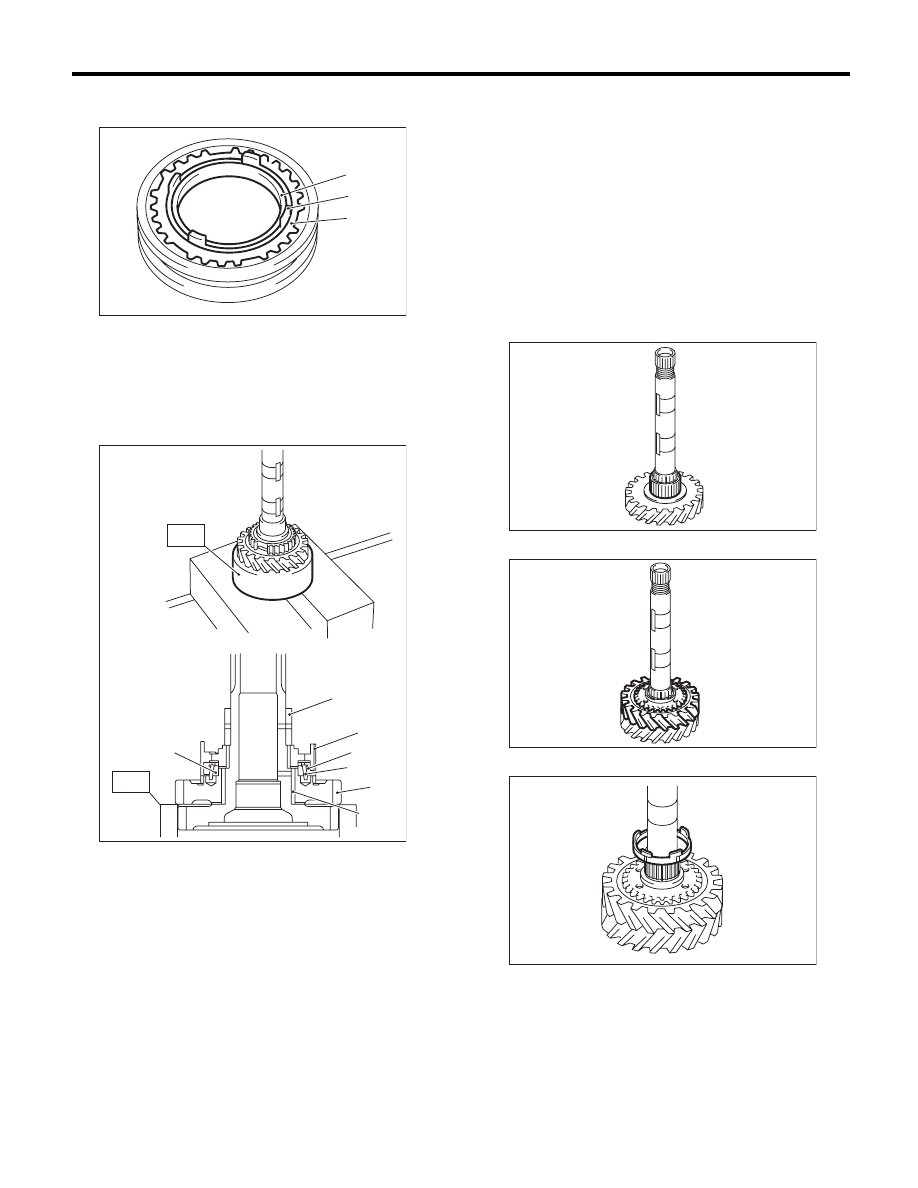
9) Remove the outer baulk ring, 2nd synchro cone
and inner baulk ring.
10) Using the ST, remove individual parts.
ST
18754AA000
REMOVER
D: ASSEMBLY
NOTE:
When replacing the following parts, replace as a
set.
• Sleeve and hub
• Outer baulk ring, 1st synchro cone and inner
baulk ring
• Outer baulk ring, 2nd synchro cone and inner
baulk ring
1) Apply adequate transmission gear oil to the main
shaft, 1st needle bearing and 1st drive gear inner
surface.
2) Install the 1st needle bearing.
3) Attach the 1st driven gear to the driven shaft.
4) Install the inner baulk ring.
(A) Outer baulk ring
(B) 2nd synchro cone
(C) Inner baulk ring
(A) 2nd bushing
(B) 1st-2nd hub
(C) Outer baulk ring
(D) 1st synchro cone
(E) Inner baulk ring
(F) 1st driven gear
(G) 1st needle bearing
MT-01502
(B)
(A)
(C)
(A)
(E)
(B)
(C)
(D)
(F)
(G)
MT-00594
ST
ST
MT-00595
MT-01503
MT-01504
6MT-82
Driven Gear Assembly
MANUAL TRANSMISSION AND DIFFERENTIAL
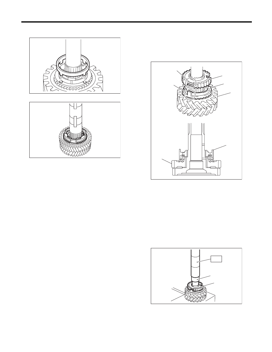
5) Match the protrusion of the 1st synchro cone to
the hole of the 1st drive gear, then install.
6) Install the outer baulk ring.
7) Install the 1st-2nd hub.
NOTE:
• Match the cut out of the 1st-2nd hub with the pro-
trusion on the outer baulk ring, then install.
• Make sure that the 1st-2nd hub is installed in the
correct direction.
8) Using the ST, install the 2nd hub.
ST
18654AA000
INSTALLER
CAUTION:
Do not apply pressure in excess of 40 kN (4.0
ton, 4.4 US ton, 3.9 Imp ton).
MT-01505
MT-00599
(A) 1st-2nd hub
(B) Outer baulk ring
(C) 1st-2nd hub cut out section
(D) Protrusion of the outer baulk ring
(E) 1st driven gear
(A) 2nd bushing
(B) 1st-2nd hub
MT-00600
(E)
(D)
(C)
(A)
(B)
(E)
(A)
MT-00601
(B)
(A)
ST
6MT-83
Driven Gear Assembly
MANUAL TRANSMISSION AND DIFFERENTIAL
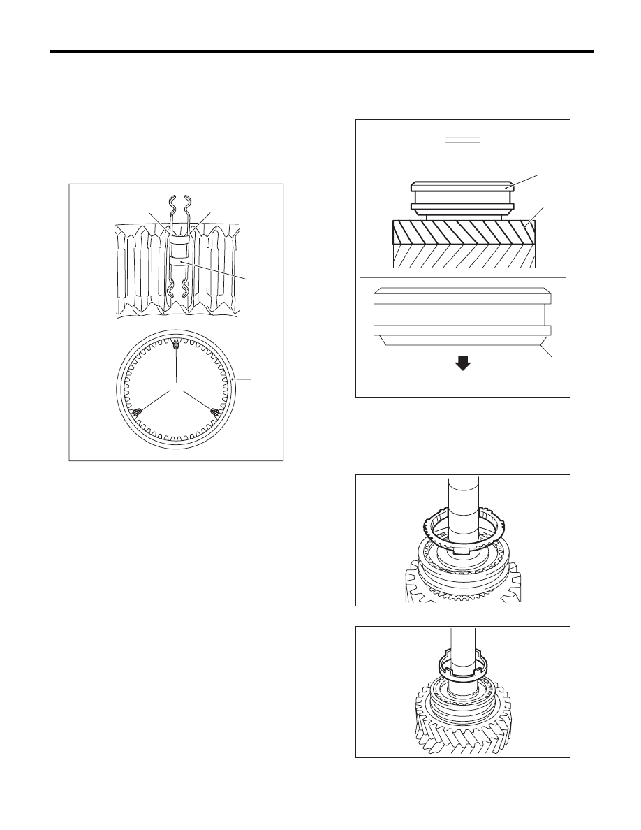
9) Make sure that the 1st drive gear can be turned
smoothly by hand. If it does not turn smoothly, re-
assemble.
10) Attach the shifting insert key to the appropriate
position of the 1st-2nd sleeve.
NOTE:
• The angle of each shifting insert key is 120°.
• Refer to the following figure to install the shifting
insert key.
11) Attach the 1st-2nd sleeve to the 1st-2nd hub.
NOTE:
Make sure that the 1st-2nd sleeve is installed in the
correct direction.
12) Install the outer baulk ring.
13) Install the 2nd synchro cone.
(A) Attach the straight part of the shifting insert key
to the sleeve convex portion.
(B) 1st-2nd shifting insert key
(C) 1st-2nd sleeve
(B)
(C)
MT-01823
(A)
(B)
(A)
(A) 1st driven gear
(B) 1st-2nd sleeve
(C) 1st driven gear side
MT-00603
(B)
(A)
(C)
(B)
MT-00604
MT-01506
6MT-84
Driven Gear Assembly
MANUAL TRANSMISSION AND DIFFERENTIAL
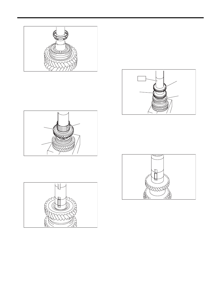
14) Install the inner baulk ring.
15) Apply adequate transmission gear oil to the
bushing, 2nd needle bearing and 2nd drive gear in-
ner surface.
16) Install the 2nd needle bearing and 2nd driven
gear.
NOTE:
Match the protrusion of the 2nd synchro cone to the
hole of the 2nd driven gear, then install.
17) Attach the key.
18) Using the ST, install the 3rd-4th driven gear.
ST
18654AA000
INSTALLER
CAUTION:
Do not apply pressure in excess of 40 kN (4.0
ton, 4.4 US ton, 3.9 Imp ton).
NOTE:
• Make sure that the 3rd-4th driven gear is in-
stalled in the correct direction.
• Match the groove on the 3rd-4th driven gear to
the key.
19) Make sure that the 2nd driven gear can be
turned smoothly by hand. If it does not turn smooth-
ly, reassemble.
20) Attach the key.
(A) 2nd needle bearing
(B) 2nd driven gear
(C) Protrusion of the 2nd synchro cone
MT-00606
MT-00607
(A)
(C)
(B)
MT-00608
(A) 4th gear
(B) 3rd gear
(C) 2nd gear
MT-00609
(A)
(C)
(B)
ST
MT-00610
Нет комментариевНе стесняйтесь поделиться с нами вашим ценным мнением.
Текст