Subaru Legacy IV (2008 year). Service manual — part 818
6MT-85
Driven Gear Assembly
MANUAL TRANSMISSION AND DIFFERENTIAL
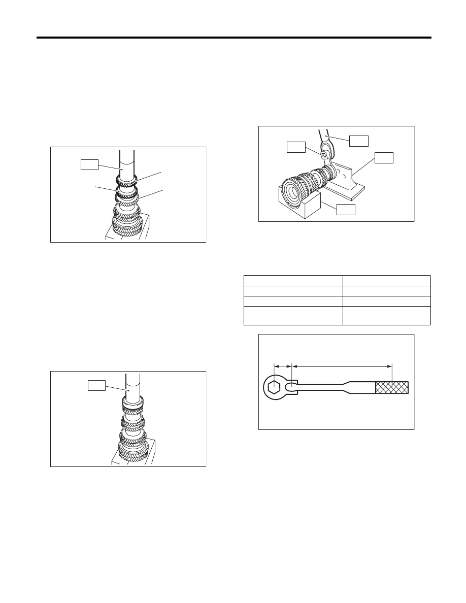
21) Using the ST, install the 5th-6th driven gear.
ST
18654AA000
INSTALLER
CAUTION:
Do not apply pressure in excess of 40 kN (4.0
ton, 4.4 US ton, 3.9 Imp ton).
NOTE:
• Make sure that the 5th-6th driven gear is in-
stalled in the correct direction.
• Match the groove on the 5th-6th driven gear to
the key.
22) Using the ST, install the ball bearing.
ST
18654AA000
INSTALLER
CAUTION:
Do not apply pressure in excess of 40 kN (4.0
ton, 4.4 US ton, 3.9 Imp ton).
NOTE:
Confirm that the ball bearing is installed in the prop-
er direction.
23) Make sure that the ball bearing turns smoothly
by hand. If it does not turn smoothly, reassemble.
24) Install a new lock nut.
25) Attach ST3 to the lock nut, attach ST to the driv-
en gear assembly, and tighten the lock nut.
ST1
18666AA000
HOLDER
ST2
18664AA000
BASE
ST3
18620AA000
ADAPTER WRENCH
ST4
18852AA000
TORQUE WRENCH
Tightening torque:
530 N·m (54.0 kgf-m, 390.9 ft-lb)
NOTE:
When using a torque wrench other than ST4, use
the calculation below to calculate and tighten the
lock nut.
T = L1 / (0.1 + L1) × 570
(A) 6th gear
(B) 5th gear
(C) 4th gear
MT-00611
(B)
ST
(A)
(C)
MT-00612
ST
T
N·m(kgf-m, ft-lb) Torque wrench setting
L1
m (in) Torque wrench length
0.1 m (3.94 in)
Length of ST
570 N·m (58.1 kgf-m, 420 ft-lb) Tightening torque (lock
nut)
(A) 0.1 m (3.94 in)
MT-00613
ST1
ST2
ST4
ST3
MT-00614
(A)
L1
6MT-86
Driven Gear Assembly
MANUAL TRANSMISSION AND DIFFERENTIAL
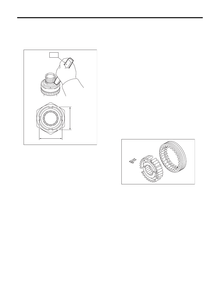
26) Using the ST, crimp the lock nut in 4 locations,
with dimensions within A 44
r0.5 mm (1.73r0.02
in).
ST
18669AA000
PUNCH DRIVEN SHAFT
NOTE:
Do not damage the crimp area of the lock nut.
E: INSPECTION
Disassembled parts should be washed clean first
with cleaning solvent and then inspected carefully.
1) Bearing
Replace the bearings in the following cases.
• Wear, rusting or damage of the bearings
• The bearing does not rotate smoothly or an ab-
normal noise is emitted when turning.
• The bearing has other defects.
2) Bushing (each gear)
Replace the bushing in following cases.
• The sliding surface is damaged or abnormally
worn.
3) Gear
Replace gears in the following cases.
• The gear teeth surface is damaged or excessive-
ly worn.
• The contact area of the baulk ring is damaged.
• The inner face of the gear is worn.
4) Baulk ring, synchro cone
Replace the baulk ring and synchro cone in the fol-
lowing cases.
• Wear, rusting or damage of the baulk ring
5) Shifting insert key
Replace the shifting insert key if deformed, exces-
sively worn or defective in any way.
MT-00615
A
A
ST
MT-00581
6MT-87
Driven Gear Assembly
MANUAL TRANSMISSION AND DIFFERENTIAL
F: ADJUSTMENT
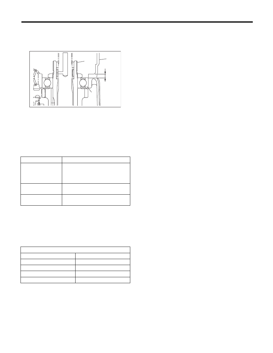
1) Measure the length “H” from the transmission
case and transfer bearing holder mating surface, to
the end face of the ball bearing.
2) Using the following calculation, calculate the
thickness of the driven gear assembly washer.
T = H – {5.8
r0.05 mm (0.23r0.002 in)} – {0.1 — 0.3
mm (0.0039 — 0.0118 in)}
3) Select 0 to 3 washers from the following table,
and adjust to the backlash that is closest to the
standard value.
Driven gear assembly axial direction backlash
standard:
0.1 — 0.3 mm (0.0039 — 0.0118 in)
(A) Transmission case
(B) Ball bearing
(C) Driven gear ASSY
t
Washer thickness
H
Length from the transmission case
and transfer bearing holder mating
surface to the end face of the ball
bearing
5.8
r0.05 mm
(0.23
r0.002 in)
Collar thickness
0.1 — 0.3 mm
(0.0039 — 0.0118 in)
Driven gear assembly axial direc-
tion backlash standard
Washer
Part No.
Thickness t mm (in)
803072030
0.15 (0.0059)
803072031
0.30 (0.0118)
803072032
0.45 (0.0177)
803072033
0.60 (0.0236)
MT-00616
(A)
H
(C)
(B)
6MT-88
Reverse Idler Gear Assembly
MANUAL TRANSMISSION AND DIFFERENTIAL
19.Reverse Idler Gear Assembly
A: REMOVAL
1) Remove the manual transmission assembly
from the vehicle. <Ref. to 6MT-32, REMOVAL,
Manual Transmission Assembly.>
2) Prepare the transmission for overhaul. <Ref. to
6MT-37, Preparation for Overhaul.>
3) Remove the neutral position switch, back-up
light switch and harness. <Ref. to 6MT-41, RE-
MOVAL, Neutral Position Switch.> <Ref. to 6MT-
39, REMOVAL, Back-up Light Switch.>
4) Remove the extension case. <Ref. to 6MT-43,
REMOVAL, Extension Case.>
5) Remove the transfer driven gear. <Ref. to 6MT-
55, REMOVAL, Transfer Driven Gear.>
6) Remove the center differential. <Ref. to 6MT-57,
REMOVAL, Center Differential.>
7) Remove the transmission case. <Ref. to 6MT-
58, REMOVAL, Transmission Case.>
8) Remove the reverse idler gear assembly. <Ref.
to 6MT-64, REMOVAL, Main Shaft Assembly.>
B: INSTALLATION
1) Select the reverse fork rod. <Ref. to 6MT-115,
ADJUSTMENT, Shifter Fork and Rod.>
2) Install the reverse idler gear assembly. <Ref. to
6MT-65, INSTALLATION, Main Shaft Assembly.>
3) Install the transmission case. <Ref. to 6MT-60,
INSTALLATION, Transmission Case.>
4) Install the center differential. <Ref. to 6MT-57,
INSTALLATION, Center Differential.>
5) Install the transfer driven gear. <Ref. to 6MT-55,
INSTALLATION, Transfer Driven Gear.>
6) Install the extension case. <Ref. to 6MT-43, IN-
STALLATION, Extension Case.>
7) Install the neutral position switch, back-up light
switch and harness. <Ref. to 6MT-41, INSTALLA-
TION, Neutral Position Switch.> <Ref. to 6MT-39,
INSTALLATION, Back-up Light Switch.>
8) Install the manual transmission assembly to the
vehicle. <Ref. to 6MT-34, INSTALLATION, Manual
Transmission Assembly.>
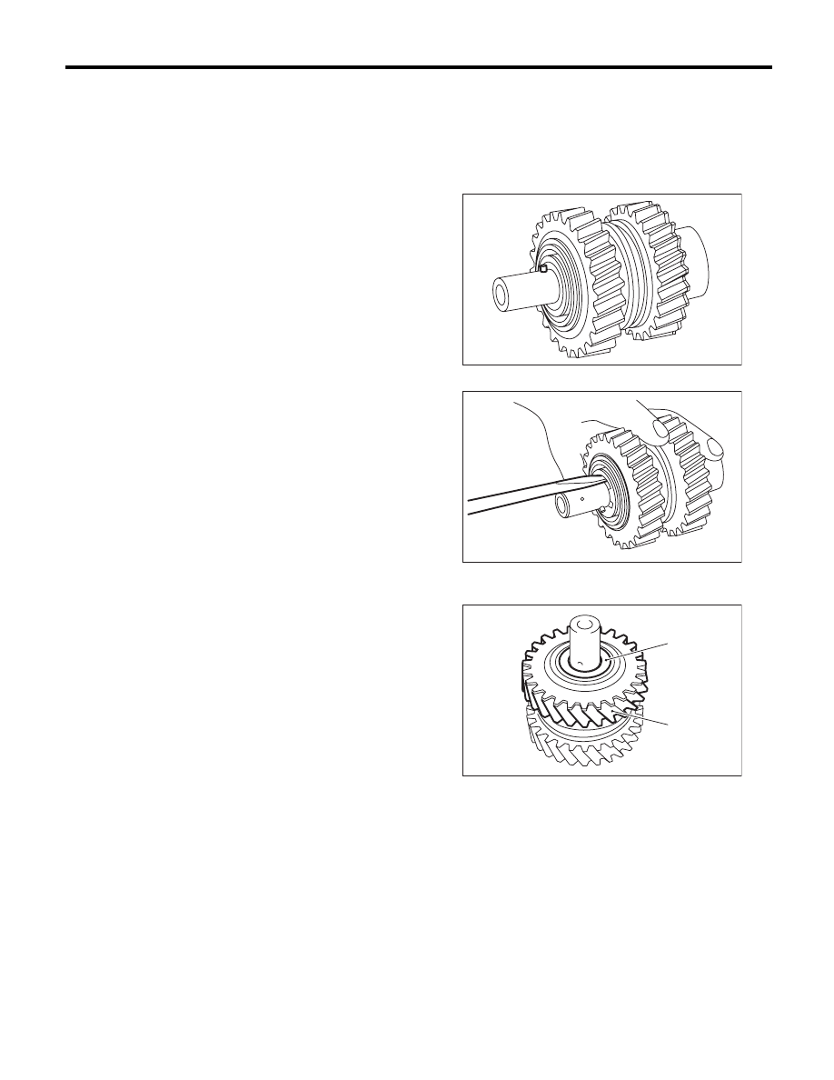
C: DISASSEMBLY
NOTE:
Sleeves and reverse gears meet at a specified po-
sition. Before disassembly, mark the meeting posi-
tion of the sleeve and hub.
1) Remove the spring pin.
2) Remove the snap ring and washer.
3) Remove the counter high & low washer and re-
verse idler gear.
(A) Counter high and low washer
(B) Reverse idler gear
MT-00617
MT-00618
MT-00619
(B)
(A)
Нет комментариевНе стесняйтесь поделиться с нами вашим ценным мнением.
Текст