Subaru Legacy IV (2008 year). Service manual — part 385

EN(H4DOTC)(diag)-361
Diagnostic Procedure with Diagnostic Trouble Code (DTC)
ENGINE (DIAGNOSTICS)
7
CHECK HARNESS BETWEEN SECONDARY
AIR COMBINATION VALVE LH AND CHAS-
SIS GROUND.
Measure the resistance between the secondary
air combination valve LH connector and chassis
ground.
Connector & terminal
(E40) No. 1 — Chassis ground:
Is the resistance less than 5
:? Go to step 8.
Repair the open
circuit of harness
between second-
ary air combination
valve LH and chas-
sis ground.
8
CHECK HARNESS BETWEEN SECONDARY
AIR COMBINATION VALVE RELAY 2 AND
SECONDARY AIR COMBINATION VALVE
LH CONNECTOR.
1) Turn the ignition switch to OFF.
2) Remove the secondary air combination
valve relay 2 from the relay box.
3) Measure the resistance of the harness
between the secondary air combination valve
relay 2 and secondary air combination valve LH
connector.
Connector & terminal
(F9) No. 8 — (E40) No. 2:
Is the resistance less than 1
:? Go to step 9.
Repair the open
circuit of the har-
ness between the
secondary air com-
bination valve relay
2 and secondary
air combination
valve LH connec-
tor.
9
CHECK SECONDARY AIR COMBINATION
VALVE RELAY 2.
1) Connect the battery to terminals No. 10 and
No. 9 of the secondary air combination valve
relay 2.
2) Measure the resistance between the sec-
ondary air combination valve relay 2 terminals.
Terminals
No. 7 — No. 8:
Is the resistance less than 1
:? Go to step 10.
Replace the sec-
ondary air combi-
nation valve relay
2. <Ref. to
EN(H4DOTC)(diag)
-8, Electrical Com-
ponent Location.>
10
CHECK SECONDARY AIR COMBINATION
VALVE RELAY 2.
Measure the resistance between the secondary
air combination valve relay 2 terminals with the
battery disconnected.
Terminals
No. 7 — No. 8:
Is the resistance 1 M
: or
more?
Go to step 11.
Replace the sec-
ondary air combi-
nation valve relay
2. <Ref. to
EN(H4DOTC)(diag)
-8, Electrical Com-
ponent Location.>
11
CHECK SECONDARY AIR COMBINATION
VALVE RELAY 2 POWER SOURCE.
1) Turn the ignition switch to ON.
2) Measure the voltage between the second-
ary air combination valve relay 2 connector and
chassis ground.
Connector & terminal
(F9) No. 7 (+) — Chassis ground (–):
(F9) No. 10 (+) — Chassis ground (–):
Is the voltage 10 V or more?
Go to step 12.
Repair the open or
ground short circuit
of power supply
circuit.
12
CHECK HARNESS BETWEEN ECM AND
SECONDARY AIR COMBINATION VALVE
RELAY 2 CONNECTOR.
1) Turn the ignition switch to OFF.
2) Disconnect the connector of ECM.
3) Measure the resistance of harness between
ECM and secondary air combination valve relay
2 connector.
Connector & terminal
(B136) No. 19 — (F9) No. 9:
Is the resistance less than 1
:? Go to step 13.
Repair the open
circuit of harness
between ECM and
secondary air com-
bination valve relay
2 connector.
Step
Check
Yes
No

EN(H4DOTC)(diag)-362
Diagnostic Procedure with Diagnostic Trouble Code (DTC)
ENGINE (DIAGNOSTICS)
EI: DTC P2443 SECONDARY AIR INJECTION SYSTEM SWITCHING VALVE
STUCK CLOSED (BANK2)
NOTE:
For the diagnostic procedure, refer to DTC P2442. <Ref. to EN(H4DOTC)(diag)-358, DTC P2442 SECOND-
ARY AIR INJECTION SYSTEM SWITCHING VALVE STUCK OPEN (BANK2), Diagnostic Procedure with
Diagnostic Trouble Code (DTC).>
13
CHECK HARNESS BETWEEN ECM AND
SECONDARY AIR COMBINATION VALVE
RELAY 2 CONNECTOR.
Measure the resistance between the secondary
air combination valve relay 2 connector and
chassis ground.
Connector & terminal
(F9) No. 9 — Chassis ground:
Is the resistance 1 M
: or
more?
Repair the poor
contact of ECM
connector.
Repair the ground
short circuit of har-
ness between
ECM and second-
ary air combination
valve relay 2 con-
nector.
Step
Check
Yes
No
EN(H4DOTC)(diag)-363
Diagnostic Procedure with Diagnostic Trouble Code (DTC)
ENGINE (DIAGNOSTICS)
EJ:DTC P2444 SECONDARY AIR INJECTION SYSTEM PUMP STUCK ON
DTC DETECTING CONDITION:
• Immediately at fault recognition
• GENERAL DESCRIPTION <Ref. to GD(H4DOTC)-232, DTC P2444 SECONDARY AIR INJECTION SYS-
TEM PUMP STUCK ON, Diagnostic Trouble Code (DTC) Detecting Criteria.>
CAUTION:
After repair or replacement of faulty parts, perform Clear Memory Mode <Ref. to EN(H4DOTC)(diag)-
52, OPERATION, Clear Memory Mode.>, and Inspection Mode <Ref. to EN(H4DOTC)(diag)-43, PRO-
CEDURE, Inspection Mode.>.
EN(H4DOTC)(diag)-364
Diagnostic Procedure with Diagnostic Trouble Code (DTC)
ENGINE (DIAGNOSTICS)
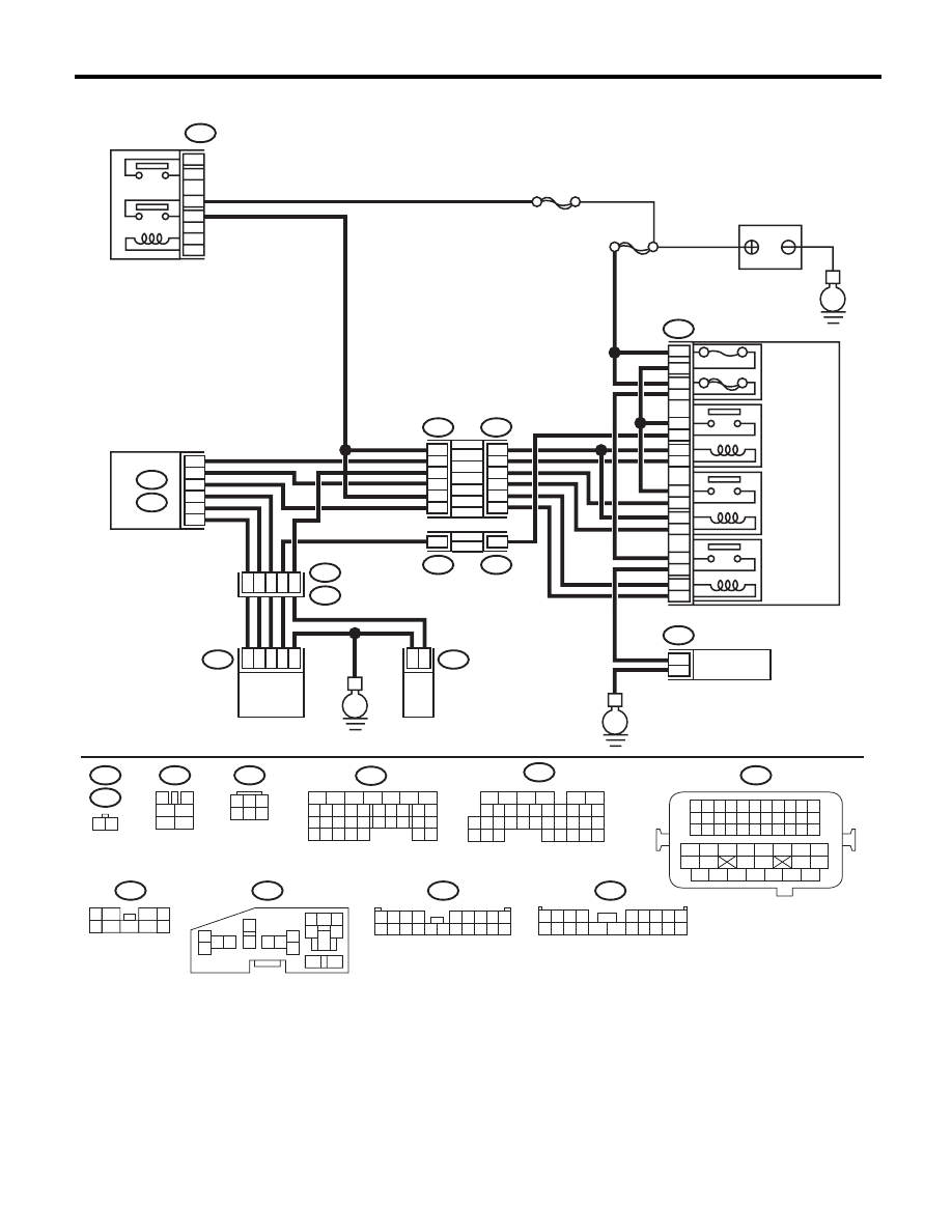
WIRING DIAGRAM:
EN-05678
B47
1
2
4
6
3
5
SBF-7
E
F9
13
12
11
14
1
2
2
1
3
4
16
15
5
6
B143
F37
B144
B21
E2
E41
E40
B134
A:
B136
C:
F37
F11
B21
E40
B47
B144
F9
B143
F37
E41
1 2 3 4
12 13 14 15
5 6 7 8
16 17 18 19
9 10 11
20 21 22
23 24 25 26 27 28 29 30 31 32 33
35
34
37
36
39
38
41
40
43
42
44
45
47
46
49
48
51
50
53
52
54
MAIN
SBF
10A
60A
9
10
8
7
E
E
11
5
20
8
C30
C19
C8
A19
A27
A29
6
1
28
47
3
2
1
6
4
1
2
9
2
16
18
14
12
10
4
14
4
F11
1 2
3
4
1
2
5
6
1
3
4 5 6
2
B134
5
6
7
8
2
1
9
4
3
10
24
22 23
25
11 12 13 14 15
26 27
28
16 17
18 19 20 21
33 34
29
32
30 31
16
10 11 12 13 14 15
25
24
30
9
8
7
17 18 19 20
28
21 22 23
29
32
31
1
2
3
4
5
6
27
26
33 34 35
B136
1
5
7
6
2
8
3
4
9
1 2 3 4
5 6 7 8 9
10 11 12 13 14
15 16 17 18 19 20
1 2 3 4
5 6 7 8 9
10 11 12 13 14 15 16 17 18 19 20
5
6
3
1
2
9
10
12
11
13
14
4
7 8
15
16
46
MAIN RELAY
BATTERY
RELAY HOLDER
SECONDARY
AIR
COMBINATION
VALVE RELAY1
SECONDARY
AIR
COMBINATION
VALVE RELAY2
SECONDARY
AIR PUMP
RELAY
SECONDARY
AIR PUMP
MAIN FUSE
BOX (M/B)
ECM
SECONDARY AIR
COMBINATION VALVE RH
(WITH BUILT-IN PRESSURE SENSOR)
SECONDARY AIR
COMBINATION
VALVE LH
Нет комментариевНе стесняйтесь поделиться с нами вашим ценным мнением.
Текст