Subaru Legacy IV (2008 year). Service manual — part 383
EN(H4DOTC)(diag)-353
Diagnostic Procedure with Diagnostic Trouble Code (DTC)
ENGINE (DIAGNOSTICS)
EF:DTC P2440 SECONDARY AIR INJECTION SYSTEM SWITCHING VALVE
STUCK OPEN (BANK1)
DTC DETECTING CONDITION:
• Two consecutive driving cycles with fault
• GENERAL DESCRIPTION <Ref. to GD(H4DOTC)-231, DTC P2440 SECONDARY AIR INJECTION SYS-
TEM SWITCHING VALVE STUCK OPEN (BANK1), Diagnostic Trouble Code (DTC) Detecting Criteria.>
CAUTION:
After repair or replacement of faulty parts, perform Clear Memory Mode <Ref. to EN(H4DOTC)(diag)-
52, OPERATION, Clear Memory Mode.>, and Inspection Mode <Ref. to EN(H4DOTC)(diag)-43, PRO-
CEDURE, Inspection Mode.>.
EN(H4DOTC)(diag)-354
Diagnostic Procedure with Diagnostic Trouble Code (DTC)
ENGINE (DIAGNOSTICS)
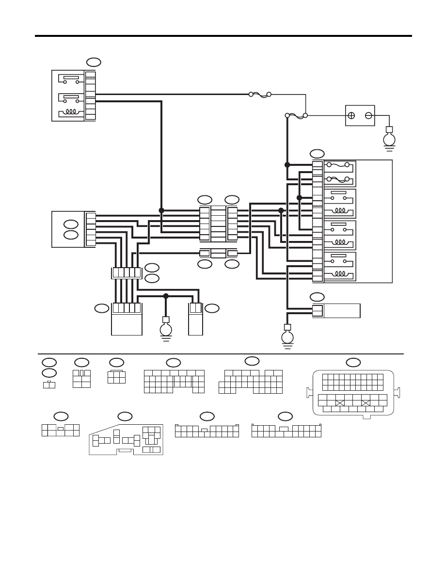
WIRING DIAGRAM:
EN-05678
B47
1
2
4
6
3
5
SBF-7
E
F9
13
12
11
14
1
2
2
1
3
4
16
15
5
6
B143
F37
B144
B21
E2
E41
E40
B134
A:
B136
C:
F37
F11
B21
E40
B47
B144
F9
B143
F37
E41
1 2 3 4
12 13 14 15
5 6 7 8
16 17 18 19
9 10 11
20 21 22
23 24 25 26 27 28 29 30 31 32 33
35
34
37
36
39
38
41
40
43
42
44
45
47
46
49
48
51
50
53
52
54
MAIN
SBF
10A
60A
9
10
8
7
E
E
11
5
20
8
C30
C19
C8
A19
A27
A29
6
1
28
47
3
2
1
6
4
1
2
9
2
16
18
14
12
10
4
14
4
F11
1 2
3
4
1
2
5
6
1
3
4 5 6
2
B134
5
6
7
8
2
1
9
4
3
10
24
22 23
25
11 12 13 14 15
26 27
28
16 17
18 19 20 21
33 34
29
32
30 31
16
10 11 12 13 14 15
25
24
30
9
8
7
17 18 19 20
28
21 22 23
29
32
31
1
2
3
4
5
6
27
26
33 34 35
B136
1
5
7
6
2
8
3
4
9
1 2 3 4
5 6 7 8 9
10 11 12 13 14
15 16 17 18 19 20
1 2 3 4
5 6 7 8 9
10 11 12 13 14 15 16 17 18 19 20
5
6
3
1
2
9
10
12
11
13
14
4
7 8
15
16
46
MAIN RELAY
BATTERY
RELAY HOLDER
SECONDARY
AIR
COMBINATION
VALVE RELAY1
SECONDARY
AIR
COMBINATION
VALVE RELAY2
SECONDARY
AIR PUMP
RELAY
SECONDARY
AIR PUMP
MAIN FUSE
BOX (M/B)
ECM
SECONDARY AIR
COMBINATION VALVE RH
(WITH BUILT-IN PRESSURE SENSOR)
SECONDARY AIR
COMBINATION
VALVE LH

EN(H4DOTC)(diag)-355
Diagnostic Procedure with Diagnostic Trouble Code (DTC)
ENGINE (DIAGNOSTICS)
Step
Check
Yes
No
1
CHECK SECONDARY AIR COMBINATION
VALVE FUSE.
Check if the secondary air combination valve
fuse (10 A) is blown out.
Is the fuse blown out?
Go to step 2.
Go to step 3.
2
CHECK HARNESS BETWEEN FUSE BOX
AND SECONDARY AIR COMBINATION
VALVE RH.
1) Remove the secondary air combination
valve fuse (10 A) from the fuse box.
2) Disconnect the connector from the second-
ary air combination valve RH.
3) Measure the resistance between the sec-
ondary air combination valve fuse and second-
ary air combination valve RH connector, and
chassis ground.
Connector & terminal
(F9) No. 5 — Chassis ground:
(E41) No. 6 — Chassis ground:
Is the resistance 1 M
: or
more?
Replace the fuse
with a new part,
and connect the
secondary air com-
bination valve RH
connector.
Go to step 3.
Repair the ground
short circuit of har-
ness between the
fuse box and the
secondary air com-
bination valve RH.
3
CHECK SECONDARY AIR COMBINATION
VALVE RH OPERATION.
1) Connect the delivery (test) mode connector.
2) Turn the ignition switch to ON.
3) Perform operation check for the secondary
air combination valve RH using the Subaru
Select Monitor.
NOTE:
Refer to “Compulsory Valve Operation Check
Mode” for more operation procedures. <Ref. to
EN(H4DOTC)(diag)-53, Compulsory Valve Op-
eration Check Mode.>
Does the secondary air combi-
nation valve RH repeatedly
switch to ON and OFF?
Go to step 4.
Go to step 6.
4
CHECK DUCT BETWEEN SECONDARY AIR
PUMP AND SECONDARY AIR COMBINA-
TION VALVE RH.
Check the duct between the secondary air
pump and secondary air combination valve RH.
Is there damage, clog or dis-
connection of the duct?
Replace, clean or
connect the duct.
Go to step 5.
5
CHECK PIPE BETWEEN SECONDARY AIR
COMBINATION VALVE RH AND CYLINDER
HEAD.
Check the pipe between the secondary air com-
bination valve RH and cylinder head.
Is there damage, clog or dis-
connection of the pipe?
Replace, clean or
connect the pipe.
Even if DTC is
detected, the cir-
cuit has returned to
a normal condition
at this time. Repro-
duce the failure,
and then perform
the diagnosis
again.
NOTE:
In this case, tem-
porary poor con-
tact of connector
may be the cause.
6
CHECK POWER SUPPLY TO SECONDARY
AIR COMBINATION VALVE RH.
1) Disconnect the connector from the second-
ary air combination valve RH.
2) In the condition of step 3, measure the volt-
age between the secondary air combination
valve RH and the chassis ground.
Connector & terminal
(E41) No. 6 (+) — Chassis ground (–):
Does the voltage repeatedly
change between 10 V and 0 V?
Replace the sec-
ondary air combi-
nation valve RH.
<Ref. to
EC(H4DOTC)-22,
Secondary Air
Combination
Valve.>
Go to step 7.

EN(H4DOTC)(diag)-356
Diagnostic Procedure with Diagnostic Trouble Code (DTC)
ENGINE (DIAGNOSTICS)
7
CHECK HARNESS BETWEEN SECONDARY
AIR COMBINATION VALVE RH AND CHAS-
SIS GROUND.
Measure the resistance between the secondary
air combination valve RH connector and chas-
sis ground.
Connector & terminal
(E41) No. 4 — Chassis ground:
Is the resistance less than 5
:? Go to step 8.
Repair the open
circuit of harness
between second-
ary air combination
valve RH and
chassis ground.
8
CHECK HARNESS BETWEEN SECONDARY
AIR COMBINATION VALVE RELAY 1 AND
SECONDARY AIR COMBINATION VALVE
RH CONNECTOR.
1) Turn the ignition switch to OFF.
2) Remove the secondary air combination
valve relay 1 from the relay box.
3) Measure the resistance of the harness
between the secondary air combination valve
relay 1 and secondary air combination valve RH
connector.
Connector & terminal
(F9) No. 3 — (E41) No. 6:
Is the resistance less than 1
:? Go to step 9.
Repair the open
circuit of the har-
ness between the
secondary air com-
bination valve relay
1 and secondary
air combination
valve RH connec-
tor.
9
CHECK SECONDARY AIR COMBINATION
VALVE RELAY 1.
1) Connect the battery to terminals No. 1 and
No. 2 of the secondary air combination valve
relay 1.
2) Measure the resistance between the sec-
ondary air combination valve relay 1 terminals.
Terminals
No. 3 — No. 4:
Is the resistance less than 1
:? Go to step 10.
Replace the sec-
ondary air combi-
nation valve relay
1. <Ref. to
EN(H4DOTC)(diag)
-8, Electrical Com-
ponent Location.>
10
CHECK SECONDARY AIR COMBINATION
VALVE RELAY 1.
Measure the resistance between the secondary
air combination valve relay 1 terminals with the
battery disconnected.
Terminals
No. 3 — No. 4:
Is the resistance 1 M
: or
more?
Go to step 11.
Replace the sec-
ondary air combi-
nation valve relay
1. <Ref. to
EN(H4DOTC)(diag)
-8, Electrical Com-
ponent Location.>
11
CHECK SECONDARY AIR COMBINATION
VALVE RELAY 1 POWER SOURCE.
1) Turn the ignition switch to ON.
2) Measure the voltage between the second-
ary air combination valve relay 1 connector and
chassis ground.
Connector & terminal
(F9) No. 4 (+) — Chassis ground (–):
(F9) No. 1 (+) — Chassis ground (–):
Is the voltage 10 V or more?
Go to step 12.
Repair the open or
ground short circuit
of power supply
circuit.
12
CHECK HARNESS BETWEEN ECM AND
SECONDARY AIR COMBINATION VALVE
RELAY 1 CONNECTOR.
1) Turn the ignition switch to OFF.
2) Disconnect the connector of ECM.
3) Measure the resistance of harness between
ECM and secondary air combination valve relay
1 connector.
Connector & terminal
(B136) No. 30 — (F9) No. 2:
Is the resistance less than 1
:? Go to step 13.
Repair the open
circuit of harness
between ECM and
secondary air com-
bination valve relay
1 connector.
Step
Check
Yes
No
Нет комментариевНе стесняйтесь поделиться с нами вашим ценным мнением.
Текст