Subaru Legacy IV (2008 year). Service manual — part 848
RS-14
Upper Link
REAR SUSPENSION
D: ASSEMBLY
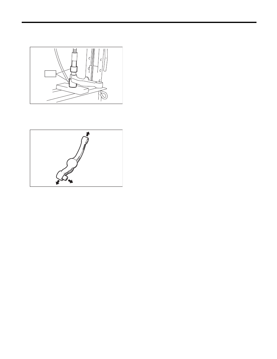
Using the ST, press the bushing into place.
ST
20099AE010
INSTALLER & REMOVER
CAUTION:
Outer side bushing has an orientation. Assem-
ble it with the longer protrusion faced to the
rear side of vehicle.
E: INSPECTION
1) Visually check the upper link for abnormal fa-
tigue or damage.
2) Visually check the bushing for abnormal fatigue
or damage.
(1) Rear arm
(2) Rear sub frame
(3) Rear side of vehicle
RS-00090
ST
RS-00121
(3)
(1)
(2)
RS-15
Rear Shock Absorber
REAR SUSPENSION
6. Rear Shock Absorber
A: REMOVAL
1) Remove the luggage floor mat. (Wagon model)
2) Roll up the trunk side trim. (Sedan model)
3) Lift up the vehicle, and then remove the rear
wheels.
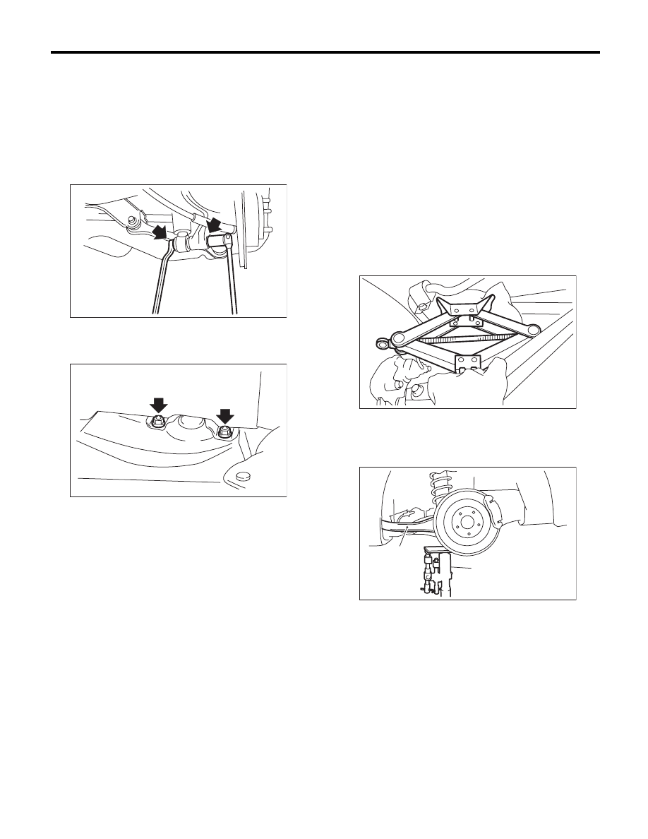
4) Remove the bolts which secure the shock ab-
sorber to rear arm.
5) Support the shock absorber using a jack.
6) Remove the nuts which secure the shock ab-
sorber mount to vehicle.
7) Remove the shock absorber.
B: INSTALLATION
1) Support the shock absorber using a jack.
2) Using new self-locking nuts, secure the shock
absorber to vehicle.
Tightening torque:
30 N·m (3.1 kgf-m, 22.4 ft-lb)
3) Set the vehicle equipped jack upside down, be-
tween the rear link and sub frame. Adjust the posi-
tion of the jack, and align the attachment position of
the rear shock absorber and rear arm. Using new
self-locking nuts, temporary tighten the bolt.
CAUTION:
Protect the rear link and sub frame from being
damaged by putting a waste cloth between the
contact surface with the jack.
4) Support the rear arm horizontally using a trans-
mission jack.
5) Using new self-locking nuts, tighten the bolt and
nut which secures the shock absorber.
Tightening torque:
62 N·m (6.3 kgf-m, 46 ft-lb)
6) Install the luggage floor mat. (Wagon model)
7) Set the trunk side trim. (Sedan model)
8) Check the wheel alignment and adjust it if nec-
essary.
RS-00065
RS-00066
(1) Rear arm
(2) Transmission jack
RS-00051
RS-00052
(1)
(2)
RS-16
Rear Shock Absorber
REAR SUSPENSION
C: DISASSEMBLY
Refer to “Front Strut” for disassembly procedure.
<Ref. to FS-22, DISASSEMBLY, Front Strut.>
D: ASSEMBLY
Refer to “Front Strut” for installation procedures.
<Ref. to FS-22, ASSEMBLY, Front Strut.>
E: INSPECTION
Refer to “Front Strut” for inspection procedures.
<Ref. to FS-23, INSPECTION, Front Strut.>
F: DISPOSAL
CAUTION:
• Before handling the shock absorber, be sure
to wear goggles to protect eyes from gas, oil
and cutting powder.
• Do not disassemble the shock absorber or
place it into a fire.
• Drill a hole into shock absorbers in case of
discarding shock absorbers filled with gas.
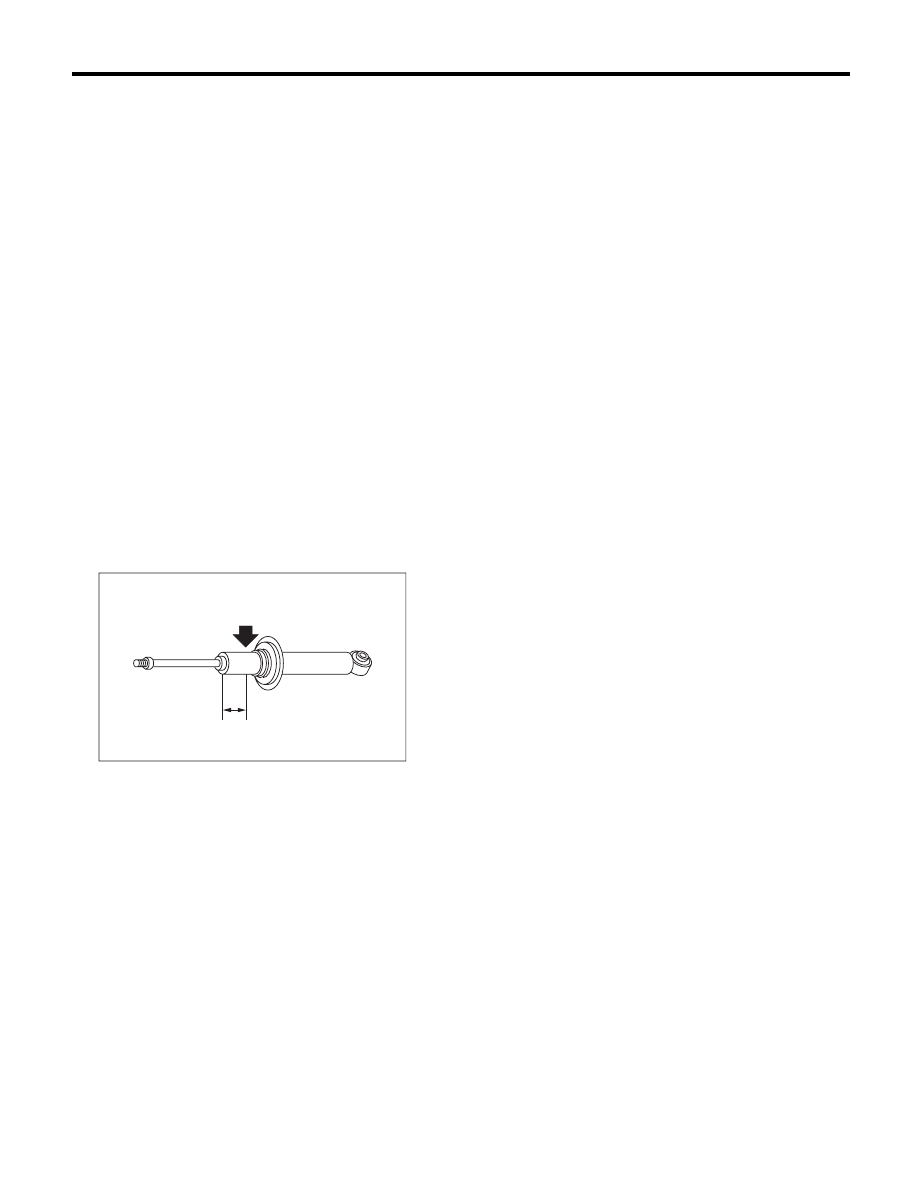
1) Place the shock absorber on a level surface with
the piston rod fully expanded.
2) Make a hole into the specified position 30 mm
(1.18 in) deep using a drill with 2 — 3 mm (0.08 —
0.12 in) diameter.
(1) 40 mm (1.57 in)
RS-00135
(1)
RS-17
Front Link
REAR SUSPENSION
7. Front Link
A: REMOVAL
1) Lift up the vehicle, and then remove the rear
wheels.
2) Support the rear arm horizontally using a trans-
mission jack.
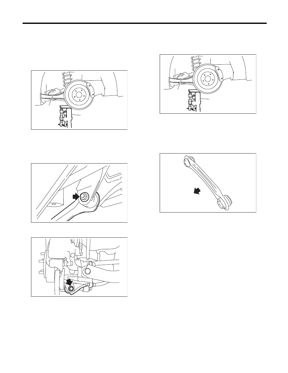
3) Remove the bolt which secures the front link to
the sub frame.
4) Remove the bolt which secures the front link to
rear arm, then remove the front link.
B: INSTALLATION
1) Support the rear arm horizontally using a trans-
mission jack.
2) Using new self-locking nuts, install the front link.
CAUTION:
Install the front link with the protruding side
facing the front side of the vehicle.
NOTE:
Inspect the wheel alignment and adjust if neces-
sary.
Tightening torque:
57 N·m (5.8 kgf-m, 42 ft-lb)
C: INSPECTION
Visually check the front link for damage and defor-
mation.
(1) Rear arm
(2) Transmission jack
RS-00052
(1)
(2)
RS-00072
RS-00073
(1) Rear arm
(2) Transmission jack
(1) Front
RS-00052
(1)
(2)
RS-00075
(1)
Нет комментариевНе стесняйтесь поделиться с нами вашим ценным мнением.
Текст