Subaru Legacy IV (2008 year). Service manual — part 846
RS-6
General Description
REAR SUSPENSION
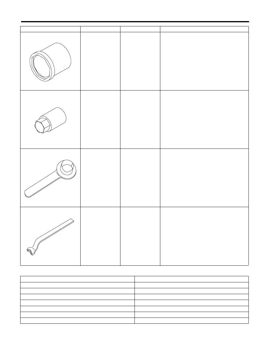
2. GENERAL TOOL
20099AE030
HELPER SOCKET
WRENCH
Used for replacing helper.
20399AG000
STRUT MOUNT
SOCKET
Used for removing and installing shock mount.
28099PA090
OIL SEAL
PROTECTOR
• Used for installing the rear drive shaft to the
rear differential.
• For oil seal protection
28099PA100
REMOVER
Used for removal of DOJ.
TOOL NAME
REMARKS
Alignment gauge
Used for measuring wheel alignment.
Alignment gauge adapter
Used for measuring wheel alignment.
Turning radius gauge
Used for measuring wheel alignment.
Toe-in gauge
Used for toe-in measurement.
Transmission jack
Used for removing and installing suspension.
Bearing puller
Used for removing bushings.
Coil spring compressor
Used for disassembling and assembling shock absorber.
ILLUSTRATION
TOOL NUMBER
DESCRIPTION
REMARKS
ST20099AE030
ST20399AG000
ST28099PA090
ST28099PA100
RS-7
Wheel Alignment
REAR SUSPENSION
2. Wheel Alignment
A: INSPECTION
NOTE:
Measure and adjust the front and rear wheel align-
ment at a time. Refer to FS section for measure-
ment and adjustment of wheel alignment. <Ref. to
FS-6, INSPECTION, Wheel Alignment.>
RS-8
Rear Stabilizer
REAR SUSPENSION
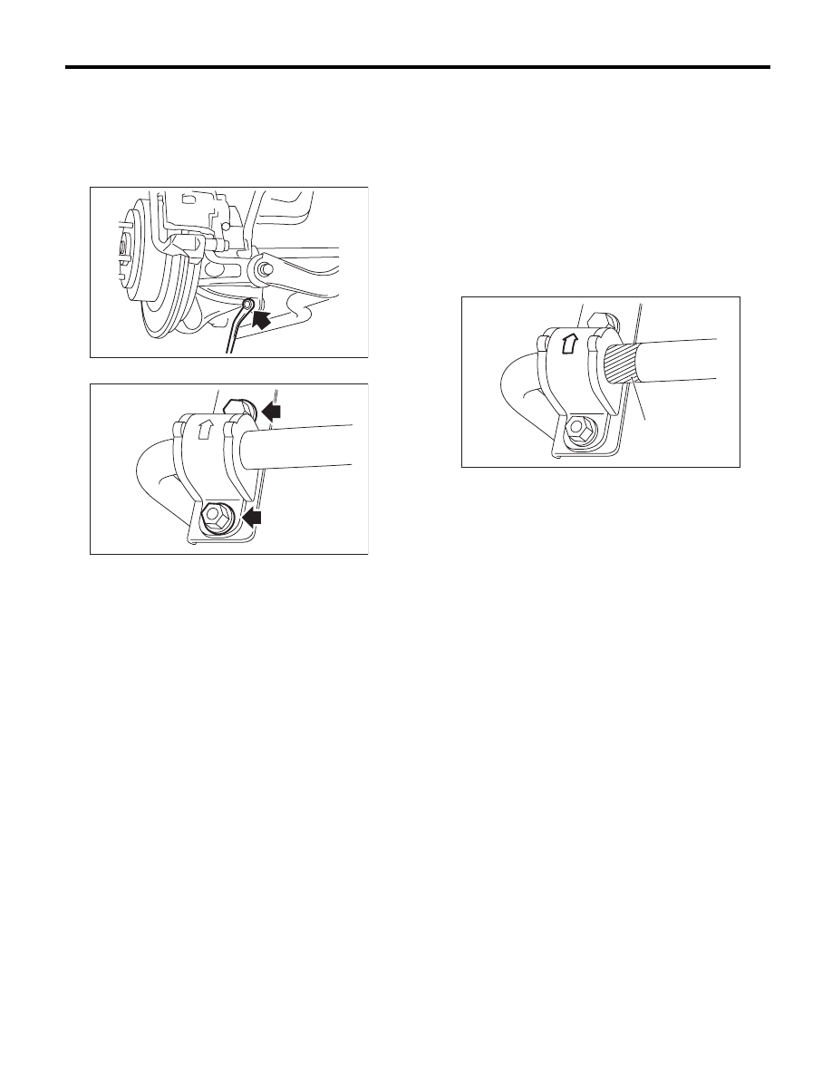
3. Rear Stabilizer
A: REMOVAL
1) Lift up the vehicle, and then remove the rear
wheels.
2) Remove the stabilizer link.
3) Remove the stabilizer bracket.
B: INSTALLATION
1) Install in the reverse order of removal.
CAUTION:
• Be sure to use a new self-locking nut.
• Ensure the stabilizer bushing and stabilizer
have the same identification colors.
• To install the stabilizer bushing, align the
paint mark end of stabilizer to the end of stabi-
lizer bushing.
• The stabilizer bracket has a set orientation.
Install it with the arrow mark facing the upper
side of the vehicle.
2) Always tighten the stabilizer bushing in the state
where the vehicle is at curb weight and the wheels
are in full contact with the ground.
Tightening torque:
Stabilizer link
44 N·m (4.5 kgf-m, 32.5 ft-lb)
Stabilizer bracket
38 N·m (3.9 kgf-m, 28 ft-lb)
C: INSPECTION
1) Check the bushing for abnormal fatigue or dam-
age.
2) Check the stabilizer link for damage.
RS-00038
RS-00217
(1) Paint mark
(1)
RS-00218
RS-9
Rear Arm
REAR SUSPENSION
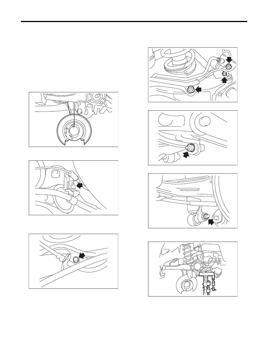
4. Rear Arm
A: REMOVAL
1) Lift up the vehicle, and then remove the rear
wheels.
2) Remove the sub frame support arm.
<Ref. to RS-20, REMOVAL, Sub Frame Support
Arm.>
3) Remove the bearing unit.
<Ref. to DS-19, REMOVAL, Rear Hub Unit Bear-
ing.>
4) Hang the back plate from sub frame.
5) Remove the bolt which secures the parking
brake cable clamp to the rear arm bracket.
6) Remove the bolt which holds the brake hose
bracket and ABS wheel speed sensor bracket to
the rear arm.
7) Remove the bolts which secure the brake hose
bracket to the rear arm. Remove the bolts which
secure the ABS wheel speed sensor to the rear
arm.
8) Remove the stabilizer link from the rear arm.
9) Remove the shock absorber from the rear arm.
10) Support the rear arm horizontally using a trans-
mission jack.
RS-00043
RS-00040
RS-00041
RS-00124
RS-00044
RS-00045
RS-00046
Нет комментариевНе стесняйтесь поделиться с нами вашим ценным мнением.
Текст