Subaru Legacy IV (2008 year). Service manual — part 776

5AT(diag)-119
General Diagnostic Table
AUTOMATIC TRANSMISSION (DIAGNOSTICS)
Engine skids when driving at 5th. Or slipping occurred.
• Fluid level and condition
• Line pressure
• Accelerator pedal position sensor
• Throttle position sensor
• CAN communication signal
• Oil pressure switch 1 and front brake solenoid valve
Slip at lock up.
• Fluid level and condition
• Line pressure
• Engine speed signal
• Turbine speed sensor 1 and turbine speed sensor 2
• Lock up solenoid valve
• CAN communication signal
Maximum vehicle speed is low.
• Fluid level and condition
• Line pressure
• Accelerator pedal position sensor
• Throttle position sensor
• CAN communication signal
• Direct clutch solenoid valve
• Vehicle speed sensor 1 and 2
There is completely no creep.
• Fluid level and condition
• Engine speed signal
• CAN communication signal
• Oil pressure switch 4 and direct clutch solenoid valve
• Line pressure
Excessive large creep.
• Engine speed signal
• CAN communication signal
• Oil pressure switch 4
Vehicle cannot be parking condition on “P” range. Parking con-
dition is not released though shifting to other ranges.
• Inhibitor switch
• Control cable adjustment
Vehicle can drive on “P” range.
• Inhibitor switch
• Fluid level and condition
• Control cable adjustment
• Line pressure
Vehicle can drive on “N” range.
• Inhibitor switch
• Fluid level and condition
• Control cable adjustment
• Line pressure
Vehicle cannot drive at any range.
• Fluid level and condition
• Line pressure
• Inhibitor switch
• Control cable adjustment
• Loosing or damaging of propeller shaft.
• Loosing or damaging of drive shaft.
Vehicle cannot drive on “D” range.
• Fluid level and condition
• Line pressure
• Inhibitor switch
• Control cable adjustment
• Loosing or damaging of propeller shaft.
• Loosing or damaging of drive shaft.
Vehicle cannot drive on “R” range.
• Fluid level and condition
• Line pressure
• Inhibitor switch
• Control cable adjustment
• Loosing or damaging of propeller shaft.
• Loosing or damaging of drive shaft.
Symptom
Problem parts

5AT(diag)-120
General Diagnostic Table
AUTOMATIC TRANSMISSION (DIAGNOSTICS)
Engine cannot start on “N” or “P” range
• Push engine switch and starter
• Control cable adjustment
• Inhibitor switch
• CAN communication line
• TCM
Engine start other than “N” or “P” range
• Push engine switch and starter
• Control cable adjustment
• Inhibitor switch
• TCM
Engine stalls.
• Fluid level and condition
• Engine speed signal
• Turbine speed sensor 1 and turbine speed sensor 2
• Lock up solenoid valve
• Line pressure
Engine stalls when shifting to “N”
o “D” and “R” range.
• Fluid level and condition
• Engine speed signal
• Turbine speed sensor 1 and turbine speed sensor 2
• Lock up solenoid valve
• Line pressure
Symptom
Problem parts
5MT-2
General Description
MANUAL TRANSMISSION AND DIFFERENTIAL
1. General Description
A: SPECIFICATION
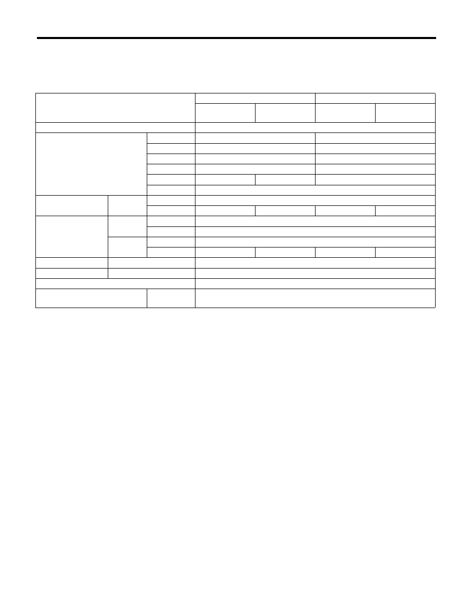
1. MANUAL TRANSMISSION AND DIFFERENTIAL
Model
2.5 L non-turbo model
2.5 L turbo model
Except for
OUTBACK
OUTBACK
Except for
OUTBACK
OUTBACK
Type
5-forward speeds and 1-reverse
Transmission gear ratio
1st
3.454
3.166
2nd
2.062
1.882
3rd
1.448
1.296
4th
1.088
0.972
5th
0.780
0.825
0.738
Reverse
3.333
Front reduction gear
Final
Type of gear
Hypoid
Gear ratio
3.900
4.111
3.900
4.444
Rear reduction gear
Transfer
Type of gear
Helical
Gear ratio
1.000
Final
Type of gear
Hypoid
Gear ratio
3.900
4.111
3.900
4.444
Front differential
Type and number of gear
Straight bevel gear (Bevel pinion: 2, Bevel gear: 2)
Center differential
Type and number of gear
Straight bevel gear (Bevel pinion: 2, bevel gear: 2 and viscous coupling)
Transmission gear oil
GL-5
Transmission gear oil capacity
Single-range
model
3.5
2 (3.7 US qt, 3.1 Imp qt)

5MT-3
General Description
MANUAL TRANSMISSION AND DIFFERENTIAL
2. TRANSMISSION GEAR OIL
Recommended oil:
GL-5 (75W-90) or equivalent
3. TRANSMISSION CASE ASSEMBLY
Drive pinion shim adjustment
Hypoid gear backlash:
0.13 — 0.18 mm (0.0051 — 0.0071 in)
Selection of main shaft rear plate
4. DRIVE PINION ASSEMBLY
Preload adjustment of thrust bearing
Starting torque:
0.3 — 0.8 N·m (0.03 — 0.08 kgf-m, 0.2 — 0.6 ft-lb)
5. REVERSE IDLER GEAR
Adjustment of reverse idler gear position
Reverse idler gear to transmission case (LH)
wall clearance:
6.0 — 7.5 mm (0.236 — 0.295 in)
After installing a suitable reverse shifter lever, ad-
just the clearance using washers.
Reverse idler gear to transmission case wall
clearance:
0 — 0.5 mm (0 — 0.020 in)
Drive pinion shim
Part number
Thickness
mm (in)
Part number
Thickness
mm (in)
32295AA031
0.150
(0.0059)
32295AA071
0.250
(0.0098)
32295AA041
0.175
(0.0069)
32295AA081
0.275
(0.0108)
32295AA051
0.200
(0.0079)
32295AA091
0.300
(0.0118)
32295AA061
0.225
(0.0089)
32295AA101
0.500
(0.0197)
Main shaft rear plate
Dimension “A” mm (in)
Part number
Mark
4.00 — 4.13
(0.1575 — 0.1626)
32294AA041
1
3.87 — 4.00
(0.1524 — 0.1575)
32294AA051
2
Adjusting washer No. 1
Part number
Thickness mm (in)
803025051
3.925 (0.1545)
803025052
3.950 (0.1555)
803025053
3.975 (0.1565)
803025054
4.000 (0.1575)
803025055
4.025 (0.1585)
803025056
4.050 (0.1594)
803025057
4.075 (0.1604)
Adjusting washer No. 2
Part number
Thickness mm (in)
803025059
3.850 (0.1516)
803025054
4.000 (0.1575)
803025058
4.150 (0.1634)
Reverse shifter lever
Part number
Mark
Remarks
32820AA070
7
Further from case wall
32820AA080
8
Standard
32820AA090
9
Closer to the case wall
Washer (20.5 × 26 × t)
Part number
Thickness
mm (in)
Part number
Thickness
mm (in)
803020151
0.4 (0.016)
803020154
1.9 (0.075)
803020152
1.1 (0.043)
803020155
2.3 (0.091)
803020153
1.5 (0.059)
—
—
Нет комментариевНе стесняйтесь поделиться с нами вашим ценным мнением.
Текст