Subaru Legacy IV (2008 year). Service manual — part 448
FU(H6DO)-11
General Description
FUEL INJECTION (FUEL SYSTEMS)
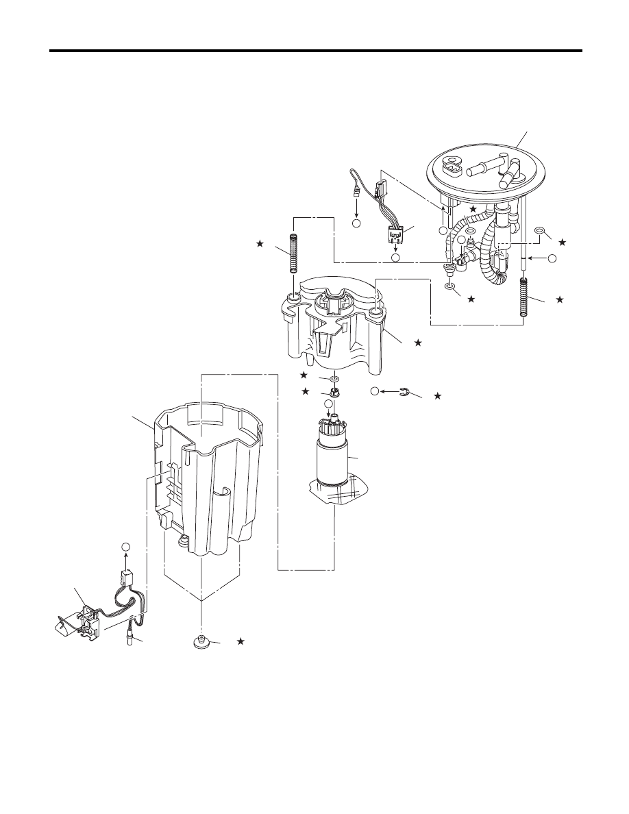
7. FUEL PUMP
(1)
Sub tank bracket ASSY
(6)
Fuel filter
(10)
Sub tank
(2)
O-ring
(7)
Clip
(11)
Cushion
(3)
O-ring
(8)
Spacer
(12)
Fuel level sensor
(4)
Fuel pump harness
(9)
Pump ASSY
(13)
Fuel temperature sensor
(5)
Spring
(1)
(4)
(5)
(6)
(2)
(8)
(9)
(10)
(11)
(7)
FU-04005
b
C
d
d
(2)
(2)
(3)
(5)
a
b
C
(12)
a
(13)
FU(H6DO)-12
General Description
FUEL INJECTION (FUEL SYSTEMS)
C: CAUTION
• Wear appropriate work clothing, including a cap, protective goggles and protective shoes when performing
any work.
• Remove contamination including dirt and corrosion before removal, installation or disassembly.
• Keep the disassembled parts in order and protect them from dust and dirt.
• Before removal, installation or disassembly, be sure to clarify the failure. Avoid unnecessary removal, in-
stallation, disassembly and replacement.
• Vehicle components are extremely hot after driving. Be wary of receiving burns from heated parts.
• Be sure to tighten fasteners including bolts and nuts to the specified torque.
• Place shop jacks or rigid racks at the specified points.
• Before disconnecting connectors of sensors or units, be sure to disconnect the ground cable from the bat-
tery.
• Place “NO OPEN FLAMES” signs near the working area.
• Prepare a container and cloth to prevent scattering of fuels when performing work where fuels can be
spilled. If the fuel spills, wipe it off immediately to prevent from penetrating into floor or flowing out for envi-
ronmental protection.
• Follow all government and local regulations concerning disposal of refuse when disposing fuel.
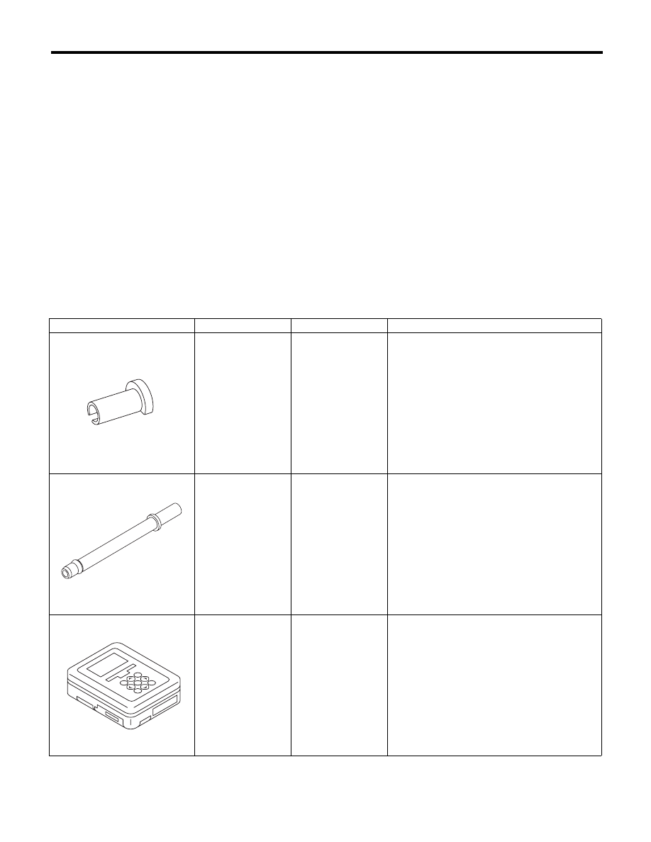
D: PREPARATION TOOL
ILLUSTRATION
TOOL NUMBER
DESCRIPTION
REMARKS
42099AE000
QUICK
CONNECTOR
RELEASE
Used for disconnecting quick connector of the
engine compartment.
18471AA000
FUEL PIPE
ADAPTER
Used for draining fuel.
1B022XU0
SUBARU SELECT
MONITOR III KIT
Used for draining fuel.
ST42099AE000
ST18471AA000
ST1B022XU0
FU(H6DO)-13
Throttle Body
FUEL INJECTION (FUEL SYSTEMS)
2. Throttle Body
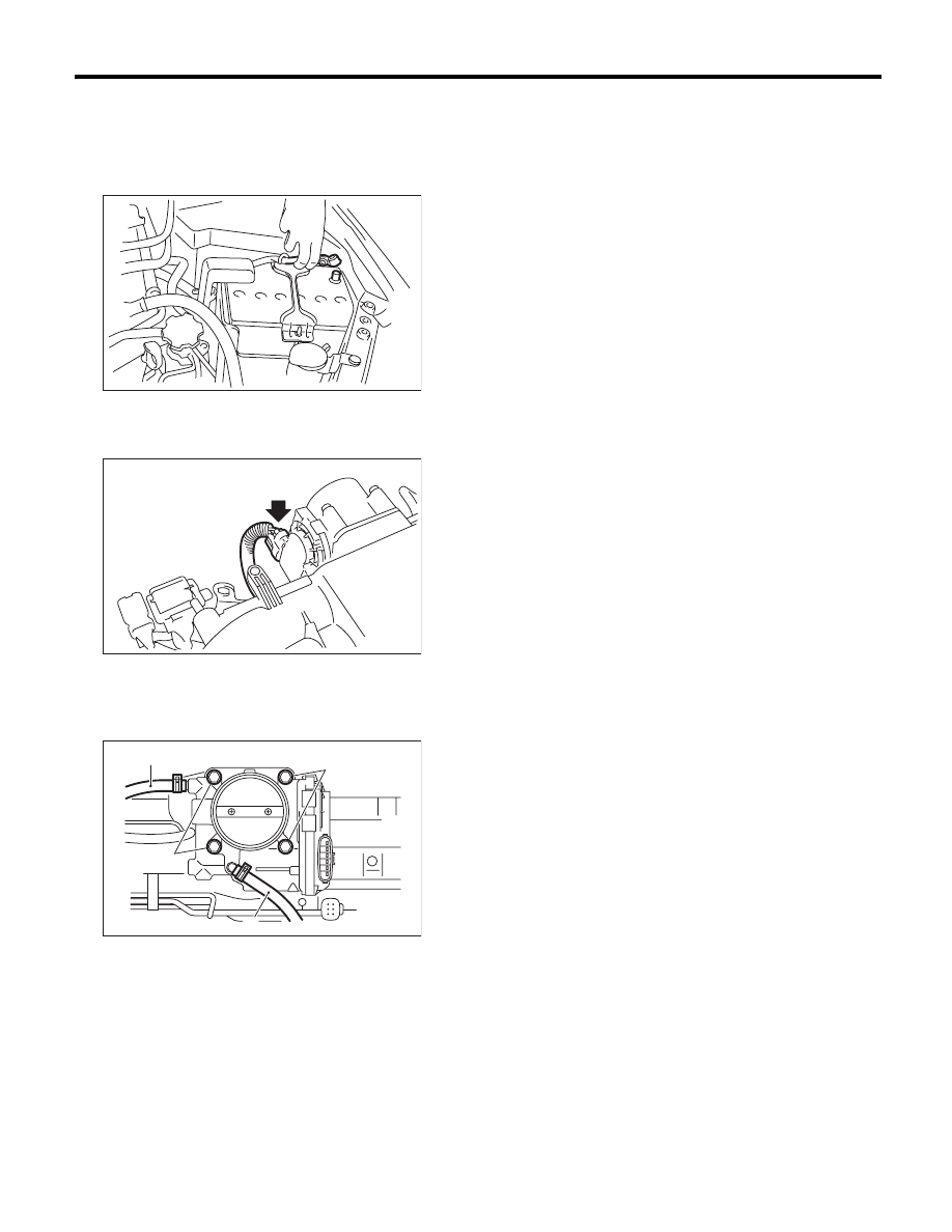
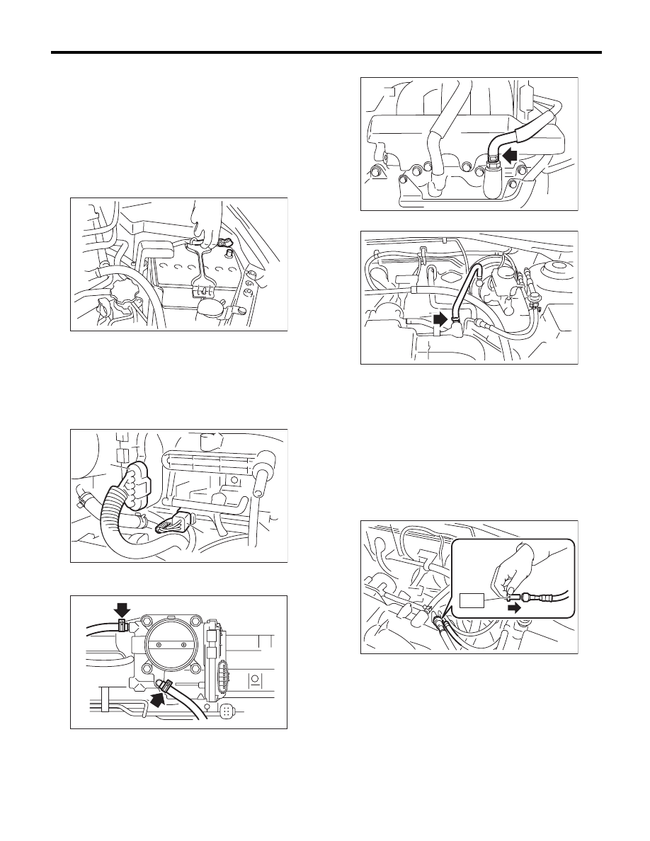
A: REMOVAL
1) Remove the collector cover.
2) Disconnect the ground cable from battery.
3) Remove the air intake chamber. <Ref. to
IN(H6DO)-7, REMOVAL, Air Intake Chamber.>
4) Disconnect the connector from throttle body.
5) Disconnect the engine coolant hoses (A) from
the throttle body.
6) Remove the bolts (B) which secure throttle body
to intake manifold.
B: INSTALLATION
Install in the reverse order of removal.
NOTE:
Use new O-rings.
Tightening torque:
8 N·m (0.8 kgf-m, 5.9 ft-lb)
IN-00203
FU-02111
FU-02112
(A)
(B)
(B)
(A)
FU(H6DO)-14
Intake Manifold
FUEL INJECTION (FUEL SYSTEMS)
3. Intake Manifold
A: REMOVAL
1) Remove the collector cover.
2) Release the fuel pressure. <Ref. to FU(H6DO)-
43, RELEASING OF FUEL PRESSURE, PROCE-
DURE, Fuel.>
3) Open the fuel filler lid, and remove the fuel filler
cap.
4) Disconnect the ground cable from battery.
5) Remove the air cleaner case and air intake
chamber. <Ref. to IN(H6DO)-5, REMOVAL, Air
Cleaner Case.> <Ref. to IN(H6DO)-7, REMOVAL,
Air Intake Chamber.>
6) Disconnect the connector (A) from the throttle
body.
7) Disconnect the engine harness connector (B).
8) Disconnect the engine coolant hoses from the
throttle body.
9) Disconnect the PCV hose.
10) Disconnect the brake booster hose.
11) Disconnect the fuel hoses from the fuel pipe.
(1) Disconnect the connector of fuel pipe by
pushing the ST in the direction of arrow.
ST
42099AE000
QUICK CONNECTOR
RELEASE
(2) Remove the clip and disconnect the evapo-
ration hose from the pipe.
CAUTION:
• Be careful not to spill fuel.
• Catch the fuel from hoses using a container
or cloth.
IN-00203
(A)
(B)
FU-02845
FU-02114
EC-02202
FU-03219
FU-02866
ST
Нет комментариевНе стесняйтесь поделиться с нами вашим ценным мнением.
Текст