Subaru Legacy IV (2008 year). Service manual — part 449
FU(H6DO)-15
Intake Manifold
FUEL INJECTION (FUEL SYSTEMS)
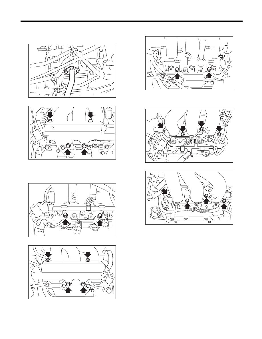
12) Remove the EGR pipe from EGR valve.
NOTE:
Be careful not to drop the gasket.
13) Remove the fuel pipe protector LH.
14) Remove the engine harness from the fuel injec-
tor pipe LH.
15) Remove the bolts which hold fuel injector pipe
LH to cylinder head.
16) Remove the fuel pipe protector RH.
17) Remove the engine harness from the fuel injec-
tor pipe RH.
18) Remove the bolts which hold the fuel injector
pipe RH to the cylinder head.
19) Remove the bolts which hold the intake mani-
fold to the cylinder head.
• LH side
• RH side
20) Remove the intake manifold.
FU-00547
FU-02117
FU-02118
FU-02119
FU-02120
FU-02121
FU-02122
FU(H6DO)-16
Intake Manifold
FUEL INJECTION (FUEL SYSTEMS)
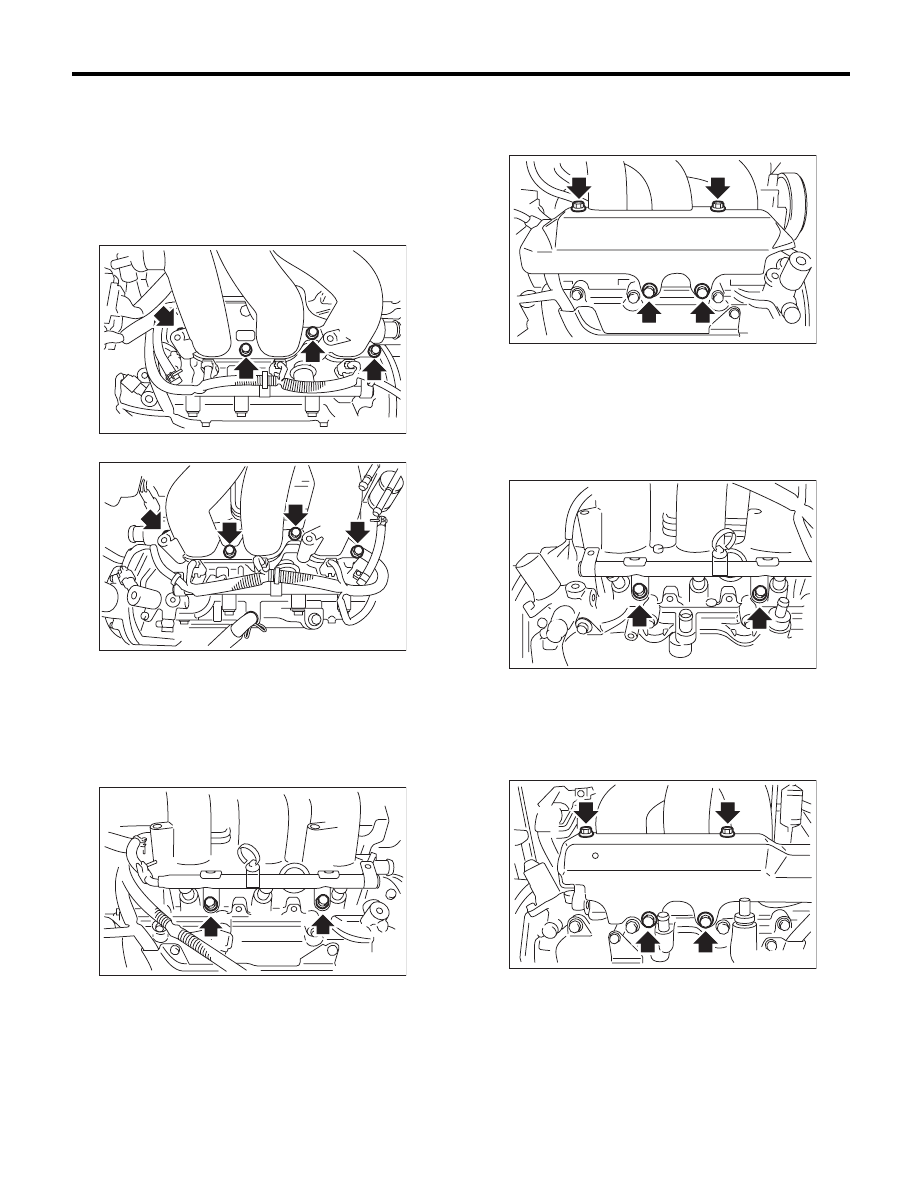
B: INSTALLATION
1) Install the intake manifold onto cylinder heads.
NOTE:
Use new O-rings.
Tightening torque:
25 N·m (2.5 kgf-m, 18.4 ft-lb)
• RH side
• LH side
2) Install the bolts which hold fuel injector pipe RH
to cylinder head.
NOTE:
Use new O-rings.
Tightening torque:
19 N·m (1.9 kgf-m, 14.0 ft-lb)
3) Install the engine harness to fuel injector pipe
RH.
4) Install the fuel pipe protector RH.
Tightening torque:
19 N·m (1.9 kgf-m, 14.0 ft-lb)
5) Install the bolts which hold fuel injector pipe LH
to cylinder head.
NOTE:
Use new O-rings.
Tightening torque:
19 N·m (1.9 kgf-m, 14.0 ft-lb)
6) Install the engine harness to fuel injector pipe
LH.
7) Install the fuel pipe protector LH.
Tightening torque:
19 N·m (1.9 kgf-m, 14.0 ft-lb)
FU-02122
FU-02121
FU-02120
FU-02119
FU-02118
FU-02117
FU(H6DO)-17
Intake Manifold
FUEL INJECTION (FUEL SYSTEMS)
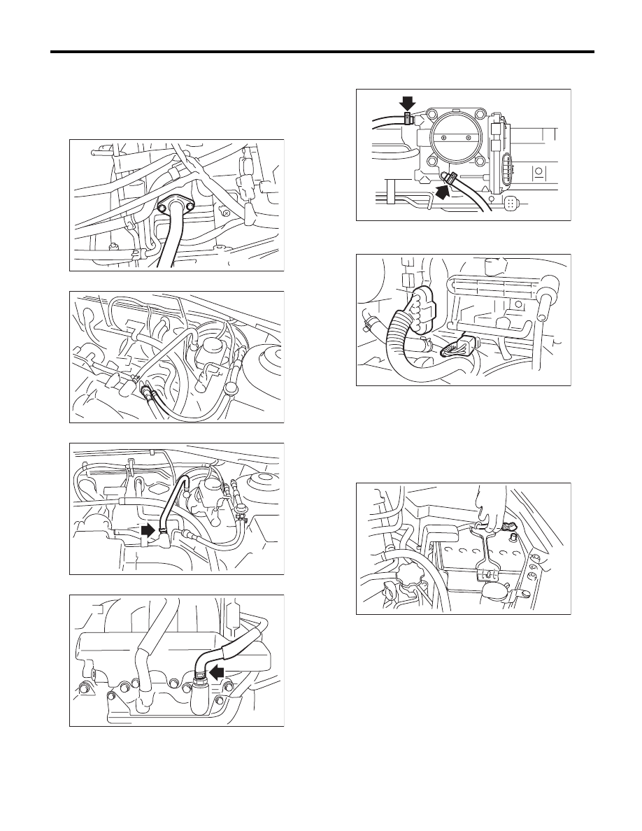
8) Install the EGR pipe to EGR valve.
NOTE:
Use a new gasket.
Tightening torque
6.4 N·m (0.7 kgf-m, 4.7 ft-lb)
9) Connect the fuel hoses to fuel pipe.
10) Connect the brake booster hose.
11) Connect the PCV hose.
12) Connect the engine coolant hoses to throttle
body.
13) Connect the connector (A) to throttle body.
14) Connect the engine harness connector (B).
15) Install the air cleaner case and air intake cham-
ber. <Ref. to IN(H6DO)-6, INSTALLATION, Air
Cleaner Case.> <Ref. to IN(H6DO)-7, INSTALLA-
TION, Air Intake Chamber.>
16) Install the fuse of fuel pump to the main fuse
box.
17) Connect the ground cable to battery.
18) Install the collector cover.
FU-00547
FU-03218
FU-03219
EC-02202
FU-02114
(A)
(B)
FU-02845
IN-00203
FU(H6DO)-18
Intake Manifold
FUEL INJECTION (FUEL SYSTEMS)
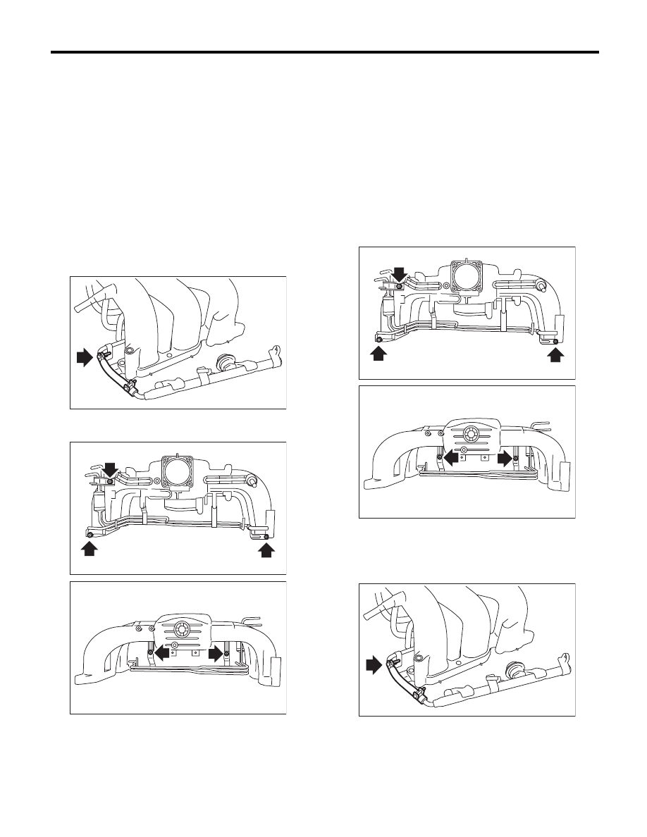
C: DISASSEMBLY
1) Remove the engine harness from intake mani-
fold.
2) Remove the throttle body. <Ref. to FU(H6DO)-
13, REMOVAL, Throttle Body.>
3) Remove the EGR valve. <Ref. to FU(H6DO)-27,
REMOVAL, EGR Valve.>
4) Remove the manifold absolute pressure sensor.
<Ref. to FU(H6DO)-25, REMOVAL, Manifold Ab-
solute Pressure Sensor.>
5) Remove the purge control solenoid valve. <Ref.
to EC(H6DO)-8, REMOVAL, Purge Control Sole-
noid Valve.>
6) Loosen the clamp which holds fuel injector pipe
to the fuel hose, and then disconnect the pipe from
fuel hose.
7) Remove the bolts which install fuel pipes on in-
take manifold.
D: ASSEMBLY
NOTE:
When assembling the nipple, apply liquid gasket.
Liquid gasket:
THREE BOND 1105 (Part No. 004403010) or
equivalent
Tightening torque:
17 N·m (1.7 kgf-m, 12.5 ft-lb)
1) Tighten the bolts which install fuel pipes on in-
take manifold.
Tightening torque:
6.4 N·m (0.7 kgf-m, 4.7 ft-lb)
2) Connect the fuel injector pipe to fuel hose, and
tighten the clamp screw.
Tightening torque:
1.25 N·m (0.1 kgf-m, 0.9 ft-lb)
3) Install the purge control solenoid valve. <Ref. to
EC(H6DO)-8, INSTALLATION, Purge Control So-
lenoid Valve.>
FU-02124
FU-02125
FU-02126
FU-02125
FU-02126
FU-02124
Нет комментариевНе стесняйтесь поделиться с нами вашим ценным мнением.
Текст