Subaru Legacy IV (2008 year). Service manual — part 692
4AT-116
AT Main Case
AUTOMATIC TRANSMISSION
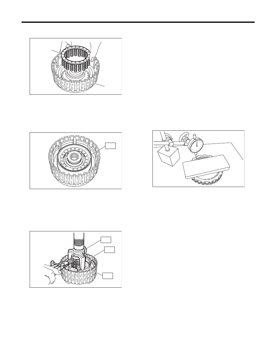
4) Install the spring retainer to the high clutch pis-
ton.
5) Attach the ST to the high clutch piston.
ST
498437000
HIGH CLUTCH PISTON
GUIDE
6) Install the cover to the high clutch piston while
making sure not to bend the high clutch piston seal.
7) Install the snap ring using ST1 and ST2.
ST1
398673600
COMPRESSOR
ST2
498627100
SEAT
ST3
498437000
HIGH CLUTCH PISTON
GUIDE
8) Measure the amount of drive plate compression
and record that value.
(1) Place the dish plate, driven plate, drive plate
and retaining plate neatly in this order on sur-
face table.
(2) Set the dial gauge to retaining plate, and
read its scale.
NOTE:
The value, which is read in the gauge at this time, is
zero point.
(3) Scale and record the weight “Z” of the flat
board that will be placed on the retaining plate.
NOTE:
• Use a stiff board which does not bend against
load as a flat board to be put on retaining plate.
• Use a flat board weighing less than 25.5 kgf
(56.2 lb).
(4) Put the flat board on retaining plate.
(5) Using the following formula, read the push/
pull gauge, and calculate “N”.
N = 250 N (25.5 kgf, 56.2 lb) – Z
N: Value indicated on push/pull gauge
250 N (25.5 kgf, 56.2 lb) : Load applied to clutch
plate
Z: Flat board weight
(A) Spring retainer
(B) High clutch drum
AT-00242
(B)
(A)
AT-00243
ST
AT-00244
ST1
ST3
ST2
AT-01720
4AT-117
AT Main Case
AUTOMATIC TRANSMISSION
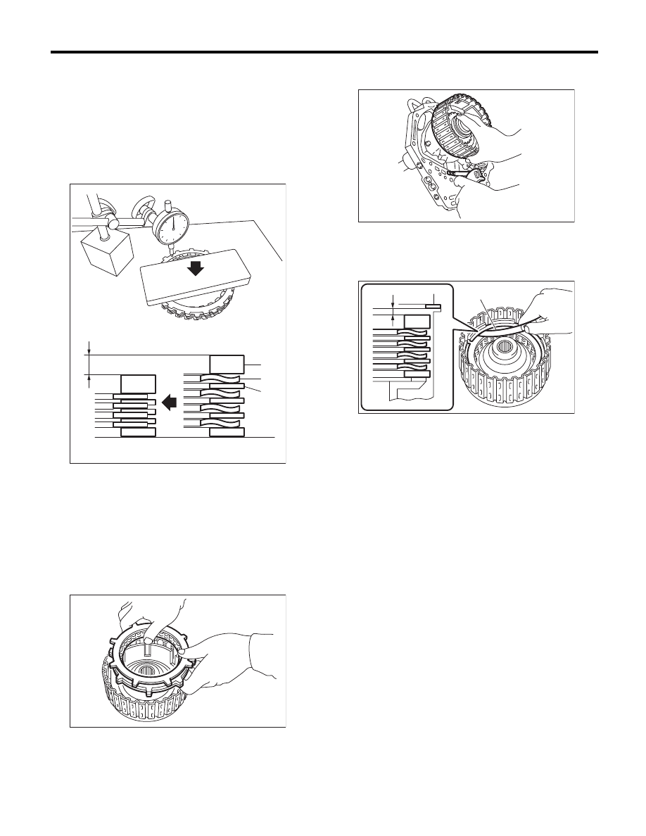
(6) Press the center of retaining plate with a
force of N using a push/pull gauge, and mea-
sure and record height “A”. Measure at three or
more locations spaced by equal distances and
take the average value.
NOTE:
If measuring in three locations, measure every
120°. If measuring in four locations, measure every
90°.
9) Install the thickest driven plate to piston side,
and then install the driven plate, drive plate, retain-
ing plate to high clutch drum.
10) Install the snap ring to high clutch drum.
11) Apply compressed air intermittently to check for
operation.
12) Check the piston stroke.
(1) Measure clearance “B” between the retain-
ing plate and snap ring. (High clutch) At this
time, do not press down the retaining plate.
A Measured value
(A) Driven plate
(B) Drive plate
(C) Retaining plate
AT-01725
(C)
(B)
(A)
A
AT-00245
B Measured value
(A) Thickness gauge
AT-00246
AT-01726
(A)
B
4AT-118
AT Main Case
AUTOMATIC TRANSMISSION
(2) Piston stroke calculation
Calculate with A and B dimensions recorded
before. If the calculated value exceeds the ser-
vice limit, replace the drive plate with a new part
and adjust it within the initial specification.
T = A + B
T: Piston stroke
A: Amount of drive plate compression
B: Clearance between retaining plate and snap
ring
Initial standard:
2.0 — 2.3 mm (0.079 — 0.091 in)
Limit thickness:
2.6 mm (0.102 in)
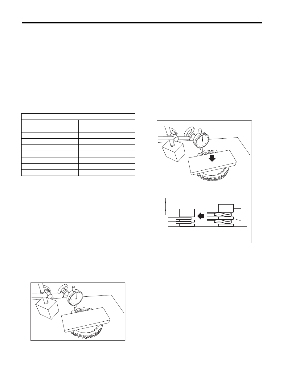
13) Choose reverse clutch retaining plate.
(1) Place the dish plate, driven plate, drive plate
and retaining plate neatly in this order on sur-
face table.
(2) Set the dial gauge to retaining plate, and
read its scale.
NOTE:
The value, which is read in the gauge at this time, is
zero point.
(3) Scale and record the weight “Z” of the flat
board that will be placed on the retaining plate.
NOTE:
• Use a stiff board which does not bend against
load as a flat board to be put on retaining plate.
• Use a flat board weighing less than 15.3 kgf
(33.7 lb).
(4) Put the flat board on retaining plate.
(5) Using the following formula, read the push/
pull gauge, and calculate “N”.
N = 150 N (15.3 kgf, 33.7 lb) – Z
N: Value indicated on push/pull gauge
150 N (15.3 kgf, 33.7 lb) : Load applied to clutch
plate
Z: Flat board weight
(6) Press the center of retaining plate with a
force of N using a push/pull gauge, and mea-
sure and record height “A”. Measure at three or
more locations spaced by equal distances and
take the average value.
NOTE:
If measuring in three locations, measure every
120°. If measuring in four locations, measure every
90°.
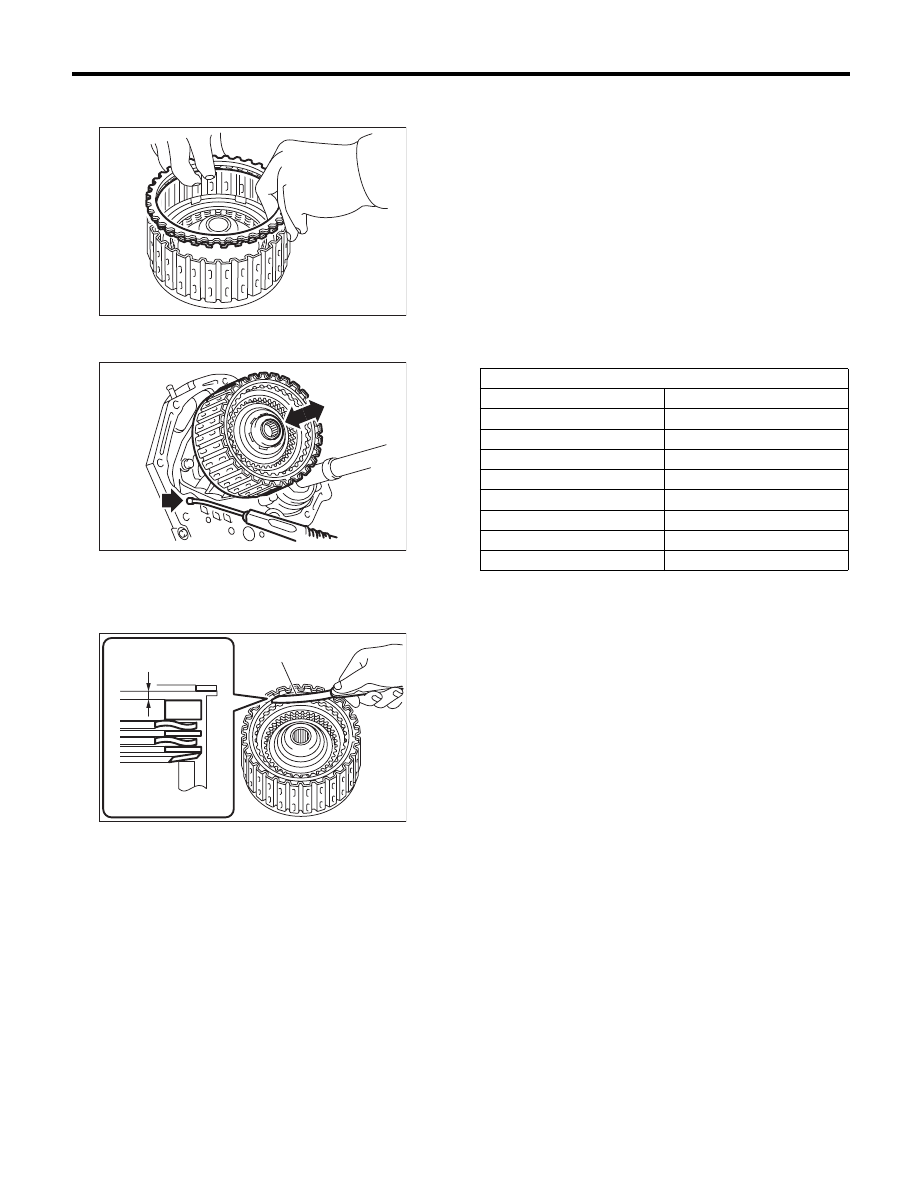
High clutch retaining plate
Part No.
Thickness mm (in)
31567AA710
4.7 (0.185)
31567AA720
4.8 (0.189)
31567AA730
4.9 (0.193)
31567AA740
5.0 (0.197)
31567AA670
5.1 (0.201)
31567AA680
5.2 (0.205)
31567AA690
5.3 (0.209)
31567AA700
5.4 (0.213)
AT-01720
A Measured value
(A) Driven plate
(B) Drive plate
(C) Retaining plate
AT-01727
(C)
(B)
(A)
A
4AT-119
AT Main Case
AUTOMATIC TRANSMISSION
(7) Install the driven plate, drive plate, retaining
plate and snap ring.
(8) Apply compressed air intermittently to check
for operation.
(9) Measure and record the clearance “B” be-
tween the retaining plate and snap ring. (Re-
verse clutch) At this time, do not press down the
retaining plate.
(10) Piston stroke calculation
Calculate with A and B dimensions recorded
before. If the calculated value exceeds the ser-
vice limit, replace the drive plate with a new part
and adjust it within the initial specification.
T = A + B
T: Piston stroke
A: Amount of drive plate compression
B: Clearance between retaining plate and snap
ring
Initial standard:
1.1 — 1.4 mm (0.043 — 0.055 in)
Limit thickness:
1.6 mm (0.063 in)
B Measured value
(A) Thickness gauge
AT-00247
AT-00248
AT-01728
(A)
B
Reverse clutch retaining plate
Part No.
Thickness mm (in)
31567AA910
4.0 (0.157)
31567AA920
4.2 (0.165)
31567AA930
4.4 (0.173)
31567AA940
4.6 (0.181)
31567AA950
4.8 (0.189)
31567AA960
5.0 (0.197)
31567AA970
5.2 (0.205)
31567AA980
5.4 (0.213)
Нет комментариевНе стесняйтесь поделиться с нами вашим ценным мнением.
Текст